VLF Tube
Receiver
Project and realization
by Giuseppe ACCARDO, Iw0BZD
On-field tests by Alan
Scremin
During
my researches on VLF and SLF bands, stared to receive geological origin
signals, I always looked for the most advanced and modern solutions. 25
years ago it was very difficult to reach some result, also the visualization
devices were primitives. These devices gave us only a look around, leaving
too many events unexplained or explained only by theory. The progress in
technology gave us high-performance integrated circuits and the capability
of direct amplification of signals, regardless of noise, impedance match
and power.
So,
why come back and use a so called obsolete component like a vacuum tube
?
 |
|
The answer is simple. First
of all the pure "ham spirit" who always guide us to look for new solutions;
in second instance the vacuum tubes were hardly improved in the past. Still
today those devices join together simplicity, low noise, strong inter modulation
rejection and resistance to strong static impulses who could destroy any
operational amplifier. On the other side, a vacuum tube needs at least
two voltage feeding: a high voltage for the plate and a low voltage (typically
6.3V) for the filament heating.
|
The idea to use a tube has always
fascinated me but handling high voltages of about some hundreds volt hanging
around has scared me since the beginning, especially because the device
has to be connected to my (expensive) laptop computer, and also because
the receiver has to be portable for extensive on-field recording sessions.
The circuit described below has
been designed to match the requirements above. As main feature, it works
with a single 12V source. It can be also feed with a little Ni-Cd or Pb
battery, like the ones used in most anti burglar systems. Due to its low
power consumption the circuit is able to work for many hours.
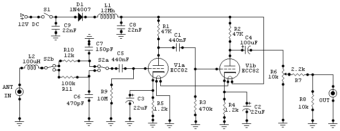
Schematic
The receiver schematic is typical.
It uses an ECC82 double triode or equivalent. For this circuit I used a
CV-4003.
Reproduction forbidden for commercial purpose (C)2003
Iw0bzd
Signals coming from the aerial
are firstly filtered by a commercial 100 uH (130 uH measured) inductor
and then applied to a couple of RC circuits to limit the bandwidth. These
two circuits, selected by an external switch, are used to limit the bandwidth
respectively from 2 mHz to 4 kHz and from 2 mHz to about 22 kHz. This trick
is useful to face the strong signals present on the band and to avoid self
detection or saturation events caused by adjacent signals.
The filters unit, through a high
capacity polyester capacitor, is coupled directly to the grid of the first
triode.
A high value resistor between
the control grid and the ground cause a weak negative polarization current.
The cathode of each tube section
is connected to the ground through a resistor connected in parallel with
an electrolytic capacitor; this makes the cathode slightly positive and
supply the right polarization to the circuit.
The coupling between the two sections
is made with a polyester capacitor. The control grid of the second tube
section is maintained to a negative voltage by a high value resistor. The
value of the capacity determines the lowest detectable frequency; this
value can vary from 220 KpF and 1 uF. With a capacity of about 1/2 uF we
can achieve a good linearity up to direct current.
The amplified signal, taken from
the anode of the second section of the tube is de-coupled by a capacitor
and regulated in amplitude by a potentiometer. After this its impedance
is adapted to match the input of the sound card.
If amplitude regulation is not
necessary it is possible also to take the signal directly after the the
capacitor.
Power
supply
Filaments
-
Using a double triode with independent heaters it is
easy to connect them in series. In this way it is possible to use a common
12V CC power supply. The filament heater is the part who requires
more power. Our tube has a common connection for the two filaments, this
make things even more easier. It is enough to connect the two edges of
the filament to the power supply leaving the common pin unconnected and
insulated.
Anodic voltage
-
Anodic voltage is applied to the plate through two
resistors. The value of these resistors is calculated to keep the tube
in its functional parameters. The chosen voltage is 12V CC. In this way
is possible to use a single power supply.
Power supply filter and protection.
-
Incoming voltage from battery or power supply pass
through a filter composed by a 12mH inductor and a couple of capacitors.
The purpose is to filter out any interference or remaining ripple. To protect
the circuit from any oversight during on-field sessions I suggest to insert
a 1N4007 diode against polarity inversion.
Due to the low power consumption
all resistors are ¼ W.
Notes
and changes
It is possible to change the grid
resistor of the first stage.
 |
|
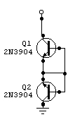
An high value if this resistor
cause an input impedance variation. In one of the prototypes, experimentally,
it has been substituted with a couple of 2N3904 (see schematic aside) to
reach some Gigaohm of impedance in coupling with a short whip aerial.
Altogether, with short extension
conventional aerial systems, higher is the resistance, lower is the noise.
Certainly in different conditions the situation will change. (Schematic
on the left shows the two transistor circuitry who substitute the control
grid resistor. Test made by Alan)
|
The modification of the input
capacitor value, connected in series to the control grid, cause the variation
of lowest frequency detectable.
 |
|
Higher is the capacitance, lower
will be the detectable frequency. Nominal values are between 220nF
and 1uF, but there is a strong correlation among capacitance, aerial and
their matching. used. The capacitor could be omitted, the circuit will
work anyway but it will become extremely sensitive to any kind of static
discharge, involving strong EM energies. (In the picture on the right
the modifications adopted to match the test whip antenna) Considerations
above comes from extensive on-field tests made by Alan Scremin.
The test were done in the better
environment conditions, with a very low noise level and far from urbanized
places.
|
In my humble opinion, I used a
low resistance value (1Mohm) obtaining remarkable results. With conventional
aerials, if we can define conventional aerial at these frequencies, the
optimal resistance value is about 10 / 100 Mohm.
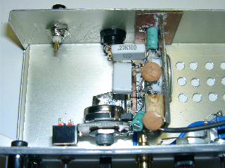
Layout
First prototype has been assembled on to a copper-clad
fiberglass foil. The components have been soldered directly on to the copper
face ("Ground" mounting). It is necessary to dispose components properly,
keeping them well ordered but accessible for further modifications.
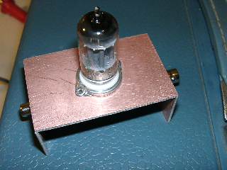
First
prototype assembly on copper-clad fiberglass frame
|
|
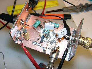
First prototype
during tests |
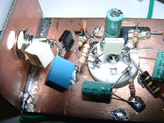
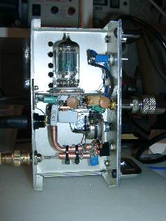
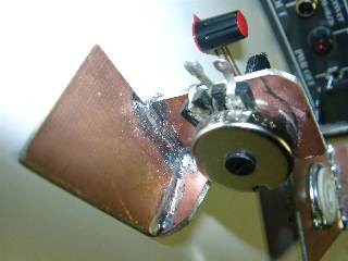
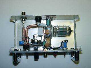
Assembly of second prototype has been done taking
more care about esthetics and functionality. It has been assembled with
another copper-clad fiberglass frame who holds up the tube and the whole
circuitry. The components have been firmly fixed to the frame. A copper
rail has been fixed to the frame. The purpose of this rail is to transport
power, avoiding wires around the chassis.
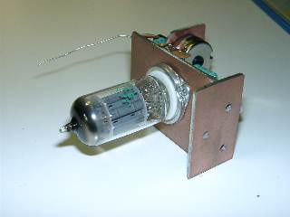
Frame of
the second prototype. |
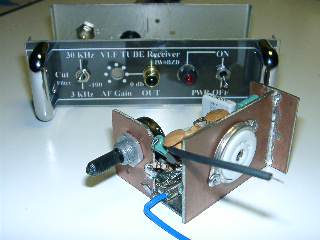
|
Complete
circuit and tube, ready for tests |
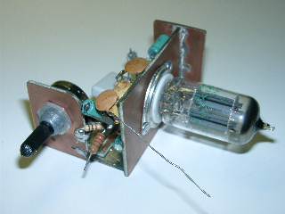
The whole prototype looks very compact and solid.
The potentiometer is housed on to the frame.
 |
|
The connections are as short
as possible, without any ground return. Every component has to be firmly
fixed to the frame.
The cables connecting coaxial
connector, filters and tube's grid have been substituted with little waveguides
made of 1mm thick copper pipe, without ground return. This solution is
not strictly necessary but helps to give even more solidity to the mechanics.
Substantially, for having something
extremely reliable, notwithstanding the esthetics that everyone wants to
give to his own realization, it is fundamental the mechanical robustness,
to eliminate all the uncertainties due to the circuit during the operations.
|
Here follows some pictures taken during the assembly
phase.
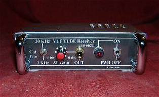
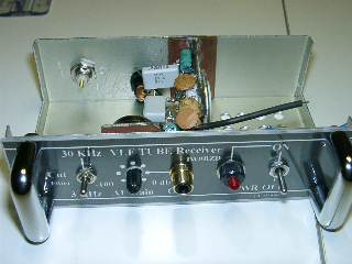
Front panel,
final.
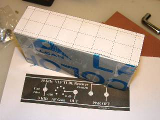
Front panel
design before drilling. |
|
Final assembly
test. |
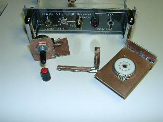
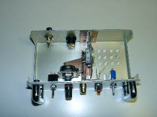
Parts ready
for assembly. |
|
Potentiometer,
housing. |
Preassembly,
final. |
|
Frame inside
the enclosure. |
Assembly
completed. |
|
Finished
prototype, top view. |
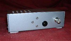
Finished
prototype, back view |
|
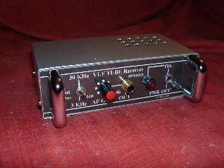
Receiver
completed |
Switch-on and
laboratory measurements
At the end of assembly it is necessary to verify
power consumption. The correct value, including heater, circuitry and LED,
is around 150mA.
After this we checked the amplification stage.
During this phase it is necessary to use an audio frequency sinusoidal
generator and an oscilloscope. These instruments will help to check the
real amplification, the quality, the phase and the cleanliness of the amplified
signal.
Without generator and oscilloscope it is possible
to generate and analyze signals with a PC, a soundcard and some free software.
 |
|
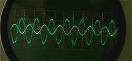
The image on the left has been taken on a vintage
Tektronics 585 and shows the input signal (channel B, the lower sine wave).
The range is 0.05V/cm.
The bigger sine wave is the amplified signal. Range
is 2V/cm. Please note the 180° phase difference between input and output.
These measurements have been done several times at different frequencies
to check the linearity of the amplifier. |
Picture above shows in particular a 90Hz sine wave.
During the tests the input voltage has been increased up to 100mV and no
saturation, distortion nor negative effect has been noticed.
Now that we know that the circuit is functional,
we are ready for an on-field test.
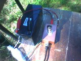
On field test
The On-field tests, lead in the splendid natural
scene of Mounts of the Laga, by Alan Scremin, demonstrate the operating
efficiency of the system.
 |
 |
|
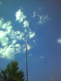
We achieved good results using a very short aerial
composed by a 2 meters high aluminum mast, connected to the receiver by
a 2 meters long coaxial cable.
Due to the insignificant size of the aerial (compared
to the wavelength) Alan started to modify the input impedance to provide
a better matching. |
He started increasing the first stage impedance
with bigger and bigger grid resistors and finally with the couple of semiconductors
showed before, to minimize the noise floor and match input and aerial impedance.
In the next picture is shown, as an example, the
variation of the noise correlated with the variation of the input resistance.
The modification involves only the resistance, all the other SW and HW
parameters are unchanged.
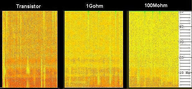
Mounts of the Laga. Reception time: 18:18
UTC, 22/06/2003
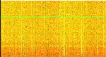
The minor
gain in the lower part of the spectrum is caused by a low coupling capacitance
(220nF) between the two stages. |
|
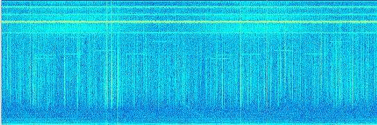
The continuous
spectrogram, up to 22KHz, point out spherics, Alpha signals and whistlers
received with the tube receiver and the 2m high whip aerial. |
The obtained spectrograms are self-explaining. Using
only 2 meters of aerial I received all the eight Schumann resonance's.
Sometimes is not possible to reach this results
even with bigger aerials.
 |
|
A quick look at the higher part of the spectrum
shows all the well known man-made signals. The system is working perfectly.
From a receiver like this we cannot expect miracles,
its gain does not compete with operational amplifiers nor with other solutions
based on field effect transistors. But the gain is not always the best
move. This receiver has an incredible robustness combined with a very low
noise. It also continues to work at very low frequencies without compromises
and always with good performances. Personal thoughts: I designed this equipment
with the purpose of searching geophysical ELF signals.
It works quite well also with short aerials but
it has been designed to be coupled (at lower impedance) with other captation
systems still under study. |
Please contact me at the address below, any feedback
is welcome.
g.accardo@tin.it
Reproduction forbidden for commercial purpose (C)2003
Iw0bzd
Acknowledgements
Many thanks to Claudio Parmigiani
for English translation and Alan Scremin for on-field tests
Return to the index