AN
EASY VLF LOOP
200Hz-20kHz
reception without transformers
by Renato Romero
and Marco Bruno
A warm afternoon, in a
summer day of this year, I was yellow painting an old hula-hop. My wife
looked at me, saying "What are you doing?". "I'm yellow painting a hoola-hop"
I answered. My wife replied: "I see, but why are you painting ... oh my
God! Another antenna!"
"Yes, but this antenna
is different from the other ones". And she, laughing: "I see, it is yellow(*)".
I explained: "With this kind of antenna I can receive signals that are
not received with the others one". And she: "It does mean you will put
all the other antennas away?" "Not exactly ..." I answered.
But my wife is right:
there are antennas at every corner in my garden. Well, this antenna will
not solve your family problems, but it can give some advantages in VLF
reception, in comparison to the Electric field receivers like RS4; especially
when the noise conditions are not very good, like in the city or near the
house. The preamplifier of this antenna is very easy to build.
(*) we have a new
theory, on antenna colour affecting radio performance, expecially in foggy
environments ;-)
WHY ANOTHER
LOOP PROJECT
The original small loop project started
some year ago, in 1995. The electric circuit is reported in "RECEPTION
TECHNIQUES / Active an passive system" on this web site. It was a good
project and a copy of this receiver has been used also by the "Astronomical
Association of Umbria" to study the correlation between VLF and Meteor
events. But its construction can give some problems: the loop antenna is
easy to build but the preamplifier has a lot of active components (many
gain stages, much noise). Some people asked me how to find the input transformer:
I used an old impedance transformer, taken by an old Phonola tube radio;
but where to buy other similar components?
Dave Ewer helped me with his loop amplifier project,
as descripted in "RECEPTION TECHNIQUES / Mobile stereo NATURAL RADIO 2".
His project, based on mine, gives better results in term of S/N ratio.
Dave in his project uses only standard components, like a Mauser device
as transformer.
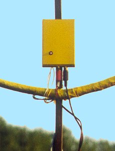
The project here presented was based on ideas by
Marco IK1ODO, and doesn't uses any transformer. The loop is connected to
the preamplifier circuit directly and the circuit contains only one active
component. |
|
 |
The signal output can be connected directly to the
LINE input of the Sound Blaster card, or LINE input of a tape recorder.
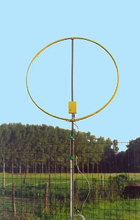
THE LOOP PROJECT
The choice of loop dimensions must take two factors
in account: to have an antenna big enough to be sensitive and small
enough to be transported or installed on a balcony without disturbing too
much the view.The choice of the support fell again on a plastic hula hop
because of the economy in materials, conserving a clean look. Dimensions
and turns number have been calculated with Rjeloop3.exe by G4FGQ.
 |
The program works assuming a square loop, while
the hula hop is round, so a square has been calculated with the same area,
resulting in a side of about 66 cm.The loop has 40 turns of copper
wire of 0.6 mm2 section for a total of 106 m and a resulting inductance
value of 3.2 mH.
Mechanical details are not given here since we
are talking about a simple shielded coil in air. The hula-hop tube was
cut on the outer rim to allow the insertion of the wire, one turn at a
time. The shield is made from aluminum foil wrapped around the whole loop,
except for 10 cm in its superior part where the shield is interrupted.
Everything was covered with adhesive PVC tape to protect from bad weather
and painted with a protective enamel. The shield is not indispensable (see
later), during all trials I haven't seen any difference between
the antenna with shield and without it. The final result is shown in picture
and is esthetically very similar to to the RCM preceding model.
THE CIRCUIT
The circuit uses a low-noise and stable op-amp,
the well known OP27.
EASYLOOP, Electric
scheme |
 |
Compared with other common devices like the TL081
or µA741, this opamp has interesting characteristics. The intrinsic
noise voltage is very low at 3nV/sqr(Hz), to be compared with 18nV/sqr(Hz)
for the quiet TL081 or 90nV/sqr(Hz) for the µA741! To improve this
value you need special and sophisticated circuits. The input noise current
is also very low, so you may use it on very low impedances like loops.
An impedance step-up transformer is simply not needed.
The circuit is simple, being derived from the configuration
used with low-impedance dynamic microphones. There is an important difference
between this circuit and other seen previously: the loop is terminated
in a zero impedance (the virtual ground at the input of the op-amp). So,
the useful signal is the current developed in the loop; other designs use
the voltage developed on the loop, wich is terminated on a high impedance.
Using a low-Z amplifier allows operation to low frequency using small loops,
and the sensitivity is very good.
The overall DC voltage gain is determined by the
ratio between the 27k negative feedback resistor (pins 2-6) and the DC
resistance of the loop (few ohm). It has to be determined experimentally
if you decide to alter the number of turns, or the size of wire, to achieve
DC stability and sufficient gain.
Input capacitors and the 330pF one limit the frequency
response of this loop to about 22 kHz, and stop MF and HF interferences.
The 27k resistor between pins 2 and 3 acts only
in case of disconnection of the loop; it may be omitted. The 10k resistor
at the output limits "pops" when connecting the output of the preamplifier
to the SB input; it could also be omitted.
The circuit is powered by a single supply between
12 and 24V, and requires a single adjustment for the offset voltage. With
the loop connected to the preamplifier apply power and turn the 10k potentiometer
(ideally, a 10-turn device) to have exactly half the power supply voltage
between pin 6 and ground. Allow some minutes for thermal stabilization
of the IC.
The OP27 is not a consumer product, but is available
from distribution chains like RS or Distrelec in Europe, Jameco or Radio
Shack in the USA. The price is about $2.
Beeing the whole loop a low impedance device closed
into a short circuit, and taking in account the common mode rejection ratio
of the op-amp, the shielding is not necessary. A good shield, with a low
impedance path against ground, and a metallic box for the preamplifier
will contribute to the long life of the IC. In any case install it on a
socket, and buy more than one... we purposedly included no protections
for the IC in this project.
SOME MEASUREMENTS
Some measurements on the circuit in my implementation:
 |
|
The voltage gain decreases with F, compensating
the increasing loop sensitivity. The output signal is constant respect
to F, and is only funtion of the H vector flow thru the loop. More later
... see section 2 (to be published) for a more theoretical treatment of
the loop frequency response. |
In our case, the DC loop resistance is about 8 Ohm.
The loop has an impedance of 8+j8 Ohm at 300 Hz; this is the low frequency
corner of the system. Under this frequency the loop resistance prevails
over the reactance, and we have a 6dB/octave rolloff in the output signal.
Increasing the wire section allows going to lower
cutoff frequencies; the limit is the input noise of the OP27. In section
2 we will demonstrate that the low frequency corner is only determined
by the WEIGHT of the copper used, and not by the number of turns! (please
don't start buying shares of copper mines ... I already bought everything
with the VLF community in mind).
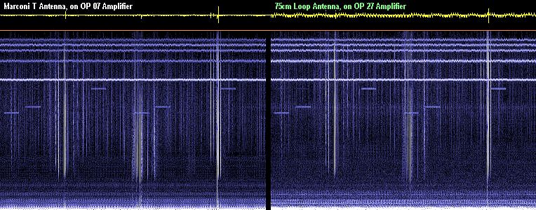
THE RESULTS
The quality of a design should
be evaluated looking at the results. The EASYLOOP is compared here
with a large Marconi "tee" antenna, giving the best results in VLF/ELF
in my installation. In the following spectrogram statics, line harmonics
and tweeks are visible. The E field antenna has more statics, and the loop
is less sensitive under 1.5 kHz. Tweeks are stronger and cleaner with the
loop; anyway, the results are very similar, but the area occupied by the
loop is about 500 times smaller.
The same signal,
received by Marconi T antenna (11m high with 45m top) compared with the
easyloop.
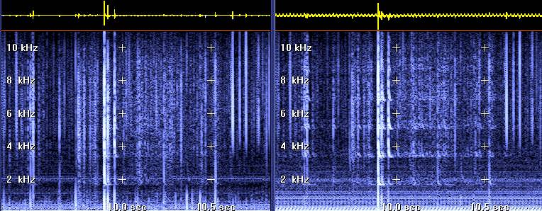
The following spectrogram covers the full 22 kHz
band allowed by the SoundBlaster. Here also the results are very similar,
and the RTTY signal around 18-20 khz are loud and clear. The russian Alpha
signals are even cleaner, with less statics.
The loop was oriented for best power line noise
rejection, and positioned at the base of the Marconi vertical antenna,
to have similar noise conditions.
CONCLUSIONS
A simple, but in our opinion innovative, small loop
antenna for VLF/ELF has been described. The design is open to experiments
and improvements, and your suggestions are welcome.
"Nihil sub sole novi" (nothing new under the sun,
say the Latins), but the simplicity of this design in relation to results
makes this project an interesting one. In urban noisy areas you may turn
the loop to minimize interference, and this resource is very useful. The
great simplicity of the preamplifier circuit, built without hard-to-find
transformers, is ideal for home building.
The loop is a low impedance device, is floating
respect to ground, and may be powered via long wires without compromising
the performance.
(© Horrible
English translation and circuit theory by Marco IK1ODO; building and experimentation
by Renato IK1QFK)
Return to the main Index