by Pierluigi Poggi IW4BLG
Adapted and enanched form the original article published by Pierluigi Poggi on Radio Rivista 04/2013 with courtesy of its director Gabriele Villa I2VGW.
This project owes its name to the fact that it's voted to allow the reception of electromagnetic fields at audio frequencies and in particular belonging to the range 1-20kHz.
What it's there to be received?
The frequencies below 20kHz are populated by a multiplicity of signals of both human nature and natural sources. We do not know who was the first to discover the presence of these signals, but it seems historically established that they were the first telegraph and telephone companies that were using those frequencies at the beginning of their business to notice these "disturbances."
Their presence was scientifically recognized in 1957 after the work of the International Geophysical Year. Since then, many studies have followed and complemented and also radio amateurs had participating in scientific advancement with their observations and experiments.
Origin of natural signals
The magnetosphere
The line of force of the magnetic field extending around our planet in order to create the magnetosphere, the place where most of the natural signals come from. This region is characterized by the fact that the movement of the charged particles is controlled basically by the terrestrial magnetic field. It has an elongated shape due to the "pressure" of the solar wind and it begins at about 200 km of altitude (similar to the F2 layer of the ionosphere) and can go up to 57000km. It worths mentioning that during the above-recalled International Geophysical Year, it was also discovered the presence of an huge areas of radiation inside the magnetosphere: these regions were called "Van Allen's band" and contain highly energetic protons and electrons.
Electrical discharges in the atmosphere.
The earth's crust is made up of minerals and "salty" liquids (oceans) and it can therefore be considered in average, a good conductor. Various measurement indicate as a day of clear blue sky provides an electric field intensity of 100 V / m, due to the negative charge that the surface of the earth tends to accumulate.
The effect of the Earth's magnetic field is likely to put in motion the charges generated by the ionization produced in the atmosphere by cosmic rays and the solar wind. The density of this current is very low (a few amperes per square meter), but, given the large surface of our planet, the total current to ground may reach an intensity of approximately 1800A. This phenomenon is known as "dark discharge" (as it is a discharge current which produces no "visible" effects or, better said, optical effects) and could neutralize the charge of the crust in a few hours in the hypothetical absence of the about 300 thunderstorms per day (approximately 26,000,000 lightning!).
When a storm is approaching, we can see that the cloud base is strongly negative. Given its proximity to the ground (only 2-3 Km in general), under them it creates an intense electric field of about 1000 V / m, due to the potential difference between the clouds and the earth, of a few million volts.
This field has the direction opposite to that existing in the case of clear sky and because of its high intensity, it creates intense ionization processes in the space between earth and clouds such as to make it locally conductor: this allows the occurrence of lightning.
Main types of natural signals:
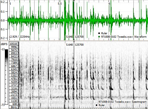 |
Tweeks & Spherics They are broad band electromagnetic signals, generated by damped waves of relatively low frequencies but rich in harmonic components; they spread long distance by means of ground waves. When heard from a speaker, Tweeks (in the picture beside) and Spherics "sound" like the chirping of a bird (hence the name), in the frequency range of 1-7 kHz. In a spectrogram they look like a descending tone, lsting 25 to 150 mS. The Tweeks are normally received in the evening, after the sunset. |
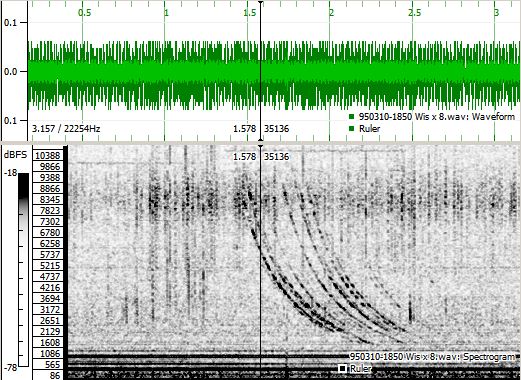 |
Whistlers The origin of these signals are, once again, the lightning. In this case, the signal generated is characterized by a very special propagation, "going out" the ionosphere and led to great distances with very low attenuation by the magnetosphere. This is one of the most interesting and unique propagation modes of VLF and ULF. The acoustic effect is very impressive and reminiscent of the sound of the dentist's drill or the sound effects of science fiction films such as Star Trek. Alongside a typicl spectrum of these emissions. |
 |
Signals of human origin In addition to the above and exciting signals of natural origin, this portion of the spectrum is populated by many human made signals, among which we can mention:
|
Theory of the sensor "E"
At these low frequencies, thus associated to wavelengths ranging from 15 to over 300 km, the realization of a "conventional antenna", meant as something similar to what we are accustomed to employ on the amateur radio bands, become almost impractical. Even if you imagine to build a "large" dipole, it will be always very small (short) compared to the wavelength to be received. Fortunately, the physics of the universe in which we live, allows us to solve the task by simply changing the approach to the problem.
The solution widely used for these frequencies, is based on the capacitive coupling with the electrical component of the electromagnetic wave to be received. In practice this solution consist on the creation of a "sensor" that couple to the radio wave, while its output is measured by difference with "another point", typically the ground potential. This solution is really broadband and very simple to implement. The only real hassle that complicate a little the life of the designer is the output impedance of the sensor, theoretically infinite. Nothing insurmountable however, as explained on the following.
Proposed scheme and practical realization
The circuit developed, despite its simplicity, it contains several precautions in the design such that it is easily replicable and with a frequency response mainly due to its circuit parameters (and therefore well known) and not to those due to realization or equipment used which could be in whole or in part, outside the control of the designer
This strong emphasis on control of the usable bandwidth is based on two fundamental needs, deeply felt by those who want to approach the experience with science and method, perhaps even combining measures, recording and data processing:
- receive signals on a well known band
- avoid being intefered by strong, out of band, signals
The second point is of particular interest because the two "worst enemies" are precisely:
- the buzz at 50Hz
- strong broadcasting on long-wave
The overall circuit is composed of three stages: the capacitive sensor, an high impedance input and an output stage for driving with very low distortion, the acquisition equipment (usually a PC sound blaster)
Everything is developed keeping in mind the easy availability of components and their reduced cost, rather than the top performances of the circuit.
Schematic
diagram of the active antenna
The capacitive sensor, is modeled into the diagram by the generator VG1 and Cant. It is made with the same mechanical device that contains the ftont end: a common tin can (in my case a former container of sugar) of about 10cm of diameter and 12 of height . This embodiment has several advantages, already tested and consolidated in past experiences (see antenna "Ri(di)cola in the bibliography), such as:
- cheap
- provide high IP
- constructive simplicity
- high capacity to the earth compared with its size
- reduced vertical size
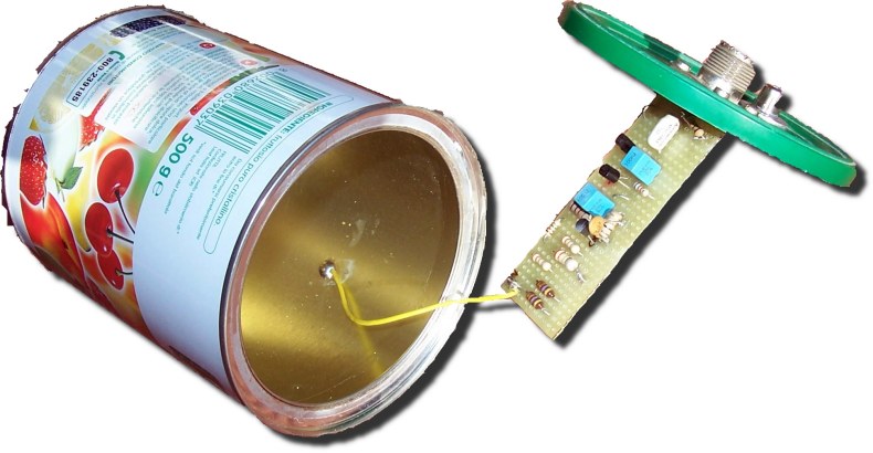
The antenna
with the circuit buit into a aluminium can
The sensor thus produced, is connected to a source follower which has a high input impedance. To do not depress this important parameter because of the bias network of the JFET and also maintain high (close to unity) the voltage gain of this stage, the configuration herewith employed is the bootstap one, here also including the output stage (T2, 6 ).
The resistors R1, 2,3,5,6, set in a solid way the idle working point of the JFET, thus ensuring that it works always (against temperature changes and the dispersions of the component) at a point of high linearity.
The output stage, which also has unity gain, has the following duties:
- to complete the isolation of the load from the generator
- adequately drive the load with low distortion
The bandwidth is defined by a multiple global feedback combined with some local filtering, described below:
L1, R8 form a low pass network, (approximately 50kHz 3dB cut-) useful to limit the amplitude of signals of the broadcasting at long and medium waves present to the input of the first stage
C5, R9 (considering the input resistance of the acquisition card) form a further high-pass filter useful, once again, to limit the overload from mains frequency and its first harmonics.
A little gloss on the output stage consisting of T2 and T6 that to some may seem "unusual". The particular configuration used is called "Sziklai." This is a similar setup, and perhaps in a sense dual to, the darlington one and often this is also called “complementary darlington” o' compoud transistor '(for English speakers) It owes its name to the great inventor George C . Sziklai which, with its more than 200 patents has become renowned for being one of the pioneers of colour television broadcasting. The main advantages of this particular configuration, is the superior thermal stability and minimal distortion. For those wishing to explore the theme, please refer to the bibliography at end of the article.
It is worth noting how this antenna, unlike other solutions, is designed to supply a load of at least 10kOhms, that is usually, a sound card and not a standard receiver which typically has instead 50Ohm of input impedance. Remember also that at these frequencies, even the best coax that connects the antenna to the sound blaster / receiver would be a purely capacitive load (50-100pF / m typical) and certainly not a transmission line with constant impedance. Therefore, the circuit is very tolerant and does not vary significantly its response also loading it with highly capacitive loads, up to a few nF.
To demonstrate the "solidity" of the circuit to the dispersions of the components it is possible to perform a Monte-Carlo analysis, which simulates in fact the realization of a large number of circuits, each one with a set of components "taken randomly from the drawer."
Here is the result:
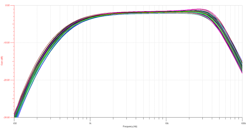
Monte Carlo
analysis of the circuit
On the usefull bandwidht of the circuits, the difference in performance remains well within 1 dB, while the out of band behaviour remain within 3dB.
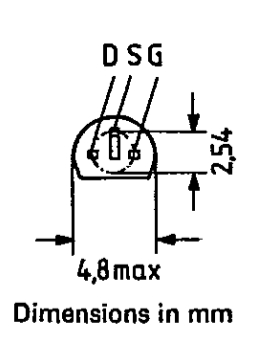
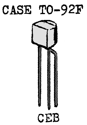
To finish this part, it can be advantageous for the reader to have summarized on a table the pinout of the active components hewith used:
 |
 |
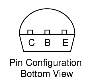 |
| BF245 | BC547-549 | BC557-559 |
Test & results
The test on the bench confirm what was specified in the simulation.
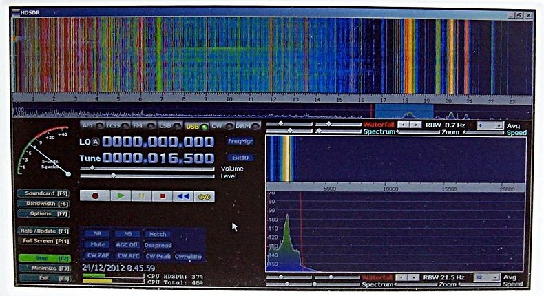
Example of
reception connecting the antenna to the sound blaster
of a laptop runninge Winrad/HDSDR.
Please note the very huge amount of man made noise
Please note the very huge amount of man made noise
The occasion for an on filed test was the activation of SAQ December 24th, 2012. The antenna, which was just 3m from the ground, has made available a good signal, managing excellently strong out of band components and showing a good dynamic performace.
Conclusions
The study of the VLF and its spectacular signals have much in common with the spirit of amateur radio, always progressive and inquiring. This device, coupled to a good quality sound card allows you to look with simplicity and economy in this wonderful world.
Ackoledgements:
A big thanks goes of course to my friend Renato IK1QFK for all the culture that has given me in this regard in recent years and to Marco IZ5IOW, Andrea IZ5TLU Franco IW3SQT as well as for the wonderful collaboration in the co-design of this project.
Bibliography:
Pierluigi Poggi, Antenne Attive, Sandit 2011
www.scribd.com/doc/3888087/78/Configurazione-Sziklai
sound.westhost.com/articles/cmpd-vs-darl.htm
en.wikipedia.org/wiki/George_Clifford_Sziklai
www.vlf.it