| Dual polarization,
balanced, VLF antenna by Pierluigi Poggi IW4BLG This article is a natural evolution of my previous two, aimed at reception of Schumann resonances and generic VLF. If you have got a bit of interest, here's another incentive to study the matter. Effective and simple, the receiving structures proposed so far suffered some limitations such as:
Let's see how we can thus improve the situation without excessive complications. Proposed circuit Below you can see the proposed schematic diagram: 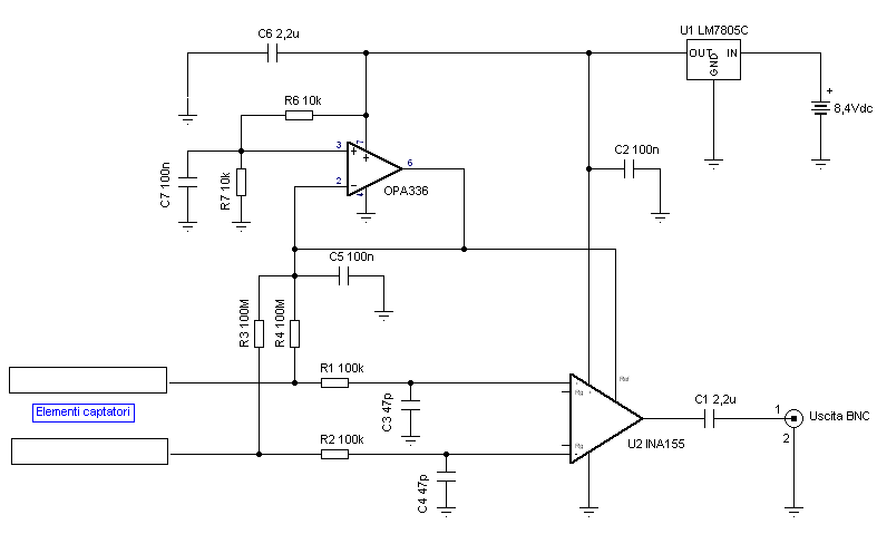 Picture
1: Schematic diagram of the active balanced VLF
antenna
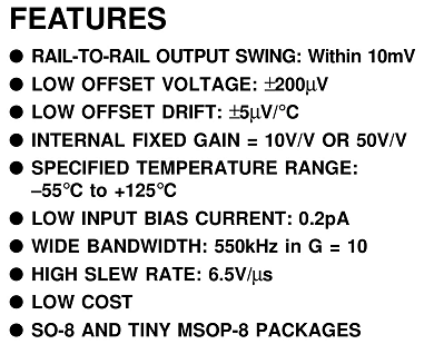
The heart of the circuit is the "instrument grade" operational amplifier Burr Brown INA155. In its simplicity, it offer very high performances at rather low cost. In particular it has a very low bias current, it handles high excursion of the voltages at the input and and at the output and not last, it has an high stability against room temperature. In addition, the device exhibits a particularly low harmonic distortion and provide high CMRR all over the frequency range. At its core, this device contains in fact four operational amplifiers with high features, connected as shown below: 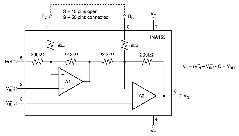 Internal
schematic of the INA155. Credits: Burr Brown
It may worth noting two interesting aspects:
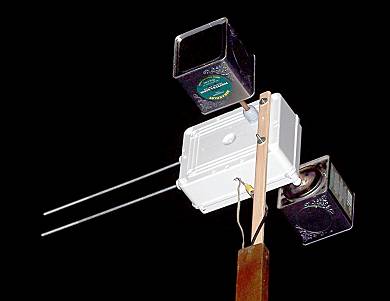
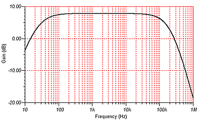
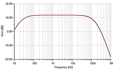
In order to maximize the dynamic is advised that in the absence of input signals, the output is keept at half the supply voltage, result obtained by applying the same voltage to the pin marked "Ref" as well as the two inputs. The two resistors of high-value R3, R4 (series of ten 10Mohm resistor) are used both for the polarization and the grounding fo the input bias current. In fact those two resistors define the input impedance of the circuit and the low frequencies response. The bias voltage is supplied by the integrated circuit OPA336 because of its high stability and very low output impedance. Let now analyse the signal path. Two probes, better described in the following, feed the two inputs of the circuit. The pairs R1-R2 and C3-C4 are two low-pass filters to limit the bandwidth and reduce the interference from powerful broadcasting on long wave. In series with the output, C1 blocks the DC component and ensures that only the variable part of the output could reach the sound blaster. The antenna, designed for temporary field use is powered by rechargeable batteries. Two interesting choices are represented by a PP3 NiMh or a 2-cell (7.4V) LiPo both offering long lasting test time. In case of fixed installation, you will need to design a solution that will not disrupt the E-field and do not inject noise in the circuit. Construction In order to keep very simple the construction, the prototype was assembled inside a weatherproof box for electrical parts. As a probes for the vertical polarization were employed two aluminum chopsticks diameter 5mm, approximately 300mm long and placed parallel one above the other spaced 60mm apart. The spacing is not critical and the choice should be aware as to increase the spacing it rises both the useful signal but also the effect of the static field. The two elements are mounted on the sides of the box, by means of two holders model PG7. This structure has a coupling capacitance to the field of approximately 4pF. For horizontal polarization, (where in general the signals are fainter), I chose to use two tea canisters, spaced approximately 250mm and aligned on the same horizontal axis. To support and connect them to the front end, I used two 8 mm copper tubes welded to the lids. This structure offers approximately 7pF of capacity. The set, as shown in the picture, looks a little “science fiction” and as a friend pointed out to me, it remember the Klingon ship. Nothing impede of course, to do it better, much better! It worth noting that the alternative connection of the probes to a single channel front end deserve some cares. The most instictive solution, namely using a DPDT relay, due to the high interelectrode capacity would ultimately heavily reduce the performance of the system! Test and results The first possible checks come from the simulation of the system. By comparison the two structures and considering the gain set to the minimum value you will get the following responses:
The response at -3dB stay almost constant between 30Hz and 120kHz. The horizontal polarization by virtue of the increased capacity of the sensors gives approximately 3dB extra gain respect the vertical one, to which you must add (not modeled) some more 12dB, due to the increased spacing of the measurement points. Once on the field, the antenna look quite interesting to use, especially for the chance to compare the two polarizations and the greater common-mode noise rejection. Here are some typical spectrograms, easily received with this antenna:
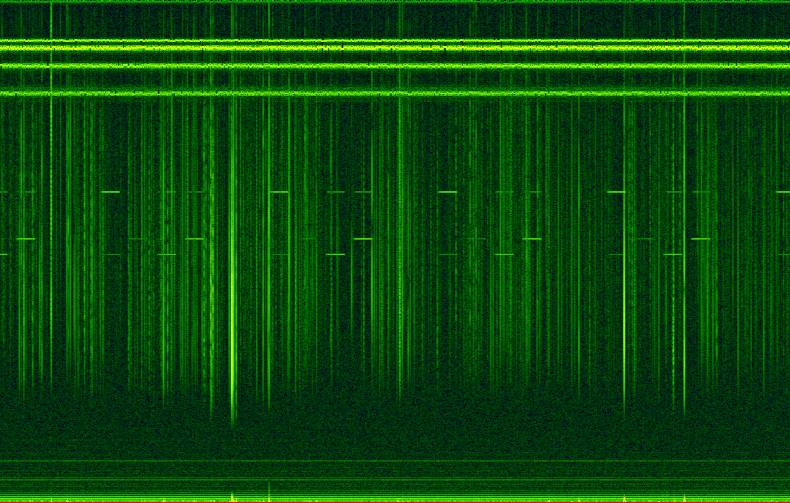
Example of vertical polarization reception post processed with Sonic Visualizer and acquired in a meadow a few hundred meters from the perimeter of my town. Note the strong signals of the stations of the Russian navigation system Alpha (the signals "hatched" approximately in the middle of the spectrogram). In horizontal polarization typically the amplitude of the static and "rtty" (which are encoded digital modulations) is reduced, while it increase the amount of noise related to the main network at 50 Hz.
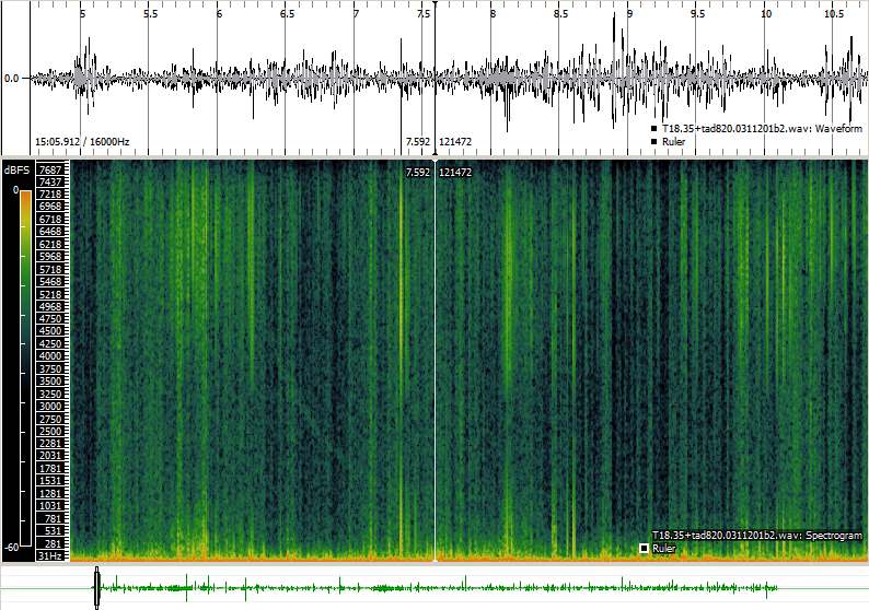
Example of a reception taken in particularly quite area on the Piacenza Apennines. Nothe the whistler (in the left half of the image processed by Renato, IK1QFK)
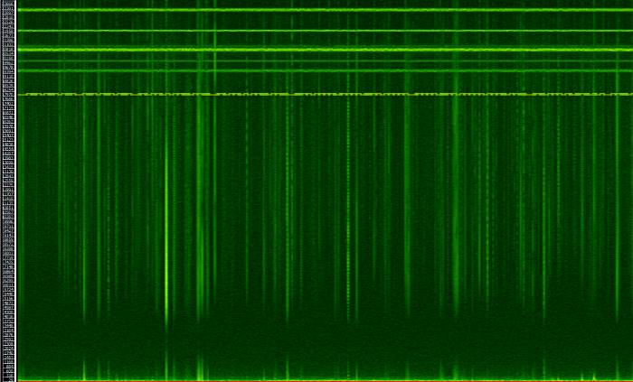
The signals along the frequency axis (vertical) that seem to "a telegram or a hatch" (but obviously they are not) are due to multipath propagation phenomena that create, from a broadband excitation of the Earth-ionosphere cavity, a "wavy" response.
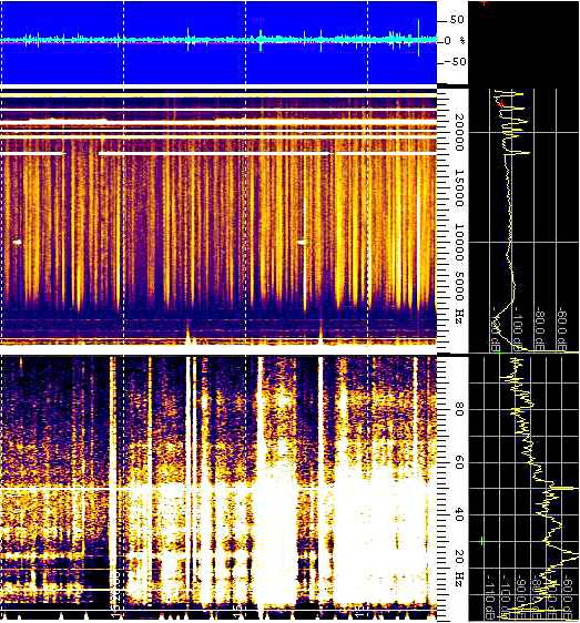
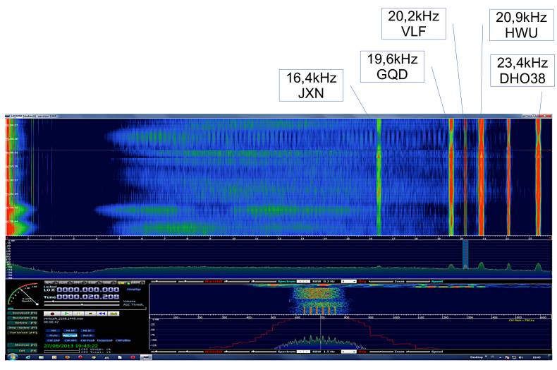
Some strong signals (processed with HDSDR) which at first glance may appear noise generated by some "electronic device" are instead human made transmission, often of a military source.
Future developments The antenna as described is already able to offer excellent opportunities, allowing good reception ... but why settle? Think for example, to focus only on the horizontal polarization and put two receiving structures at right angles to each other. Sending their signals simultaneously to stereo processing system such as SpectrumLab , you can activate the functions of " direction finding", which allow us to identify at least approximately the source of the signals ... Can this make sense? Why not try also to compare acquisitions in parallel of the two polarizations and figure out what come from the differences? The antenna to be able to work at its best should need a high system common mode rejection: how can we ensure it or improve what already presented ? The INA155 used is a good compromise between performance, cost and availability: but why not to try different solutions, perhaps by accessing most valuable devices? These are just some food for thought without boundaries. More will come... Stay Tuned!! Acknowledgments Now as always, I have the pleasant duty to thank those who helped me, supported and constructively criticized in the development of this project. In particular and in pure alphabetical order I want to remember IU3ADL Franco and Renato IK1QFK. Bibliography Pierluigi Poggi, Antenne Attive, Sandit 2011 Renato Romero, Radionatura, Sandit 2008 www.vlf.it/cr/differential_ant.htm Return to www.vlf.it index |