by Pierluigi Poggi IW4BLG
This project was triggered by the desire to make available an easy to build active antenna to boost the passion for radio listening on HF and lower band, down to VLF. Having already done some experiences, I decided to try to design a new product, easy to be replicated, reliable and with a certain degree of "personality."
The structure
In order to get handy dimensions, I decided to develop an electric field sensor, also known as "short monopole."
These kind of antennas belong to the family of E-probes and are specifically designed to being sensitive only to the electric component of the electromagnetic field. So, very little to share with “conventional” with classic dipoles, loaded towers and similar ones.
These antennas make use of the capacitive effect between two insulated conductors to "extract" the signal coming from the field.
To understand a little more about how it works, let see the following illustration:
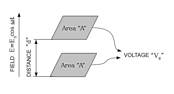
the voltage VE generated across the capacitor (and open circuit!) in the presence of a variable electric field has a value of:
This result shows how the signal (the sensitivity in other words) increases together with the spacing between the conductors, one of which, in the case of our antenna is the earth, while the other is the whip. In other words, the sensitivity of the antenna improves, as higher (thus increasing "d") is installed.
 |
|
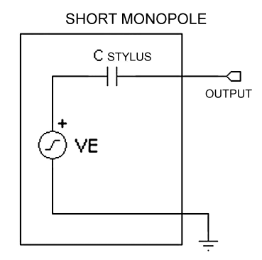
Unfortunately
against this phenomenon of conversion of the
electric field plays the capacity of the "pick-up"
as shown in the diagram, which represents the
typical equivalent circuit used to model these
antennas: where VE is the E field value and the Cstilo, is the capacitance between the capturing element and the ground. |
It worth noting that in this contextualization of the general model, the size "d" represents the effective height of the antenna.
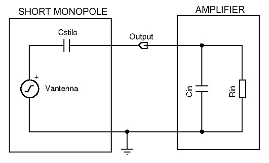 |
Once you connect
the antenna to an amplifier (or whatever kind of
frontend) , the situation becomes as shown in
Figure beside, where the transfer function (ratio
of output to input) is: It's a network with a pole and a zero placed at the origin. |
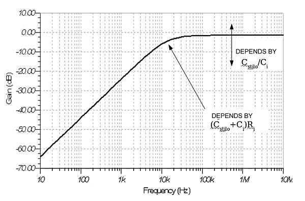
This brief mathematical analysis of the circuit together with the desire to obtain the maximum sensitivity from the system leads us to the following design considerations:
- the ratio between the two capacities defines the "maximum sensitivity" of the system
- the input capacitance of the amplifier should be negligible compared to that one of the antenna, as well as to be very high the input resistance of the amplifier
- higher the time constant:
 , the
greater will be the extent of the response at low
frequencies
, the
greater will be the extent of the response at low
frequencies
The whole frame can be summarized graphically as follows:
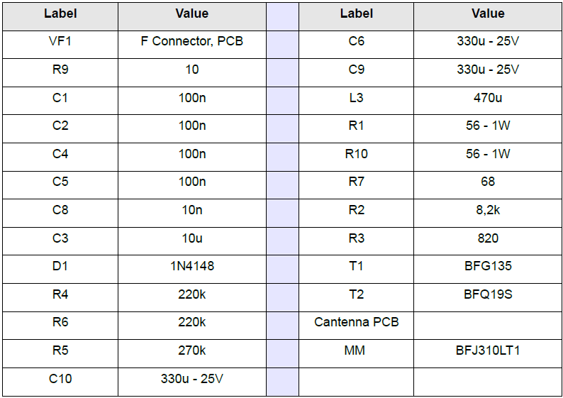
The schematic diagram
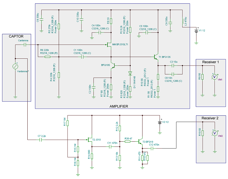
The circuit proposed is the following one:
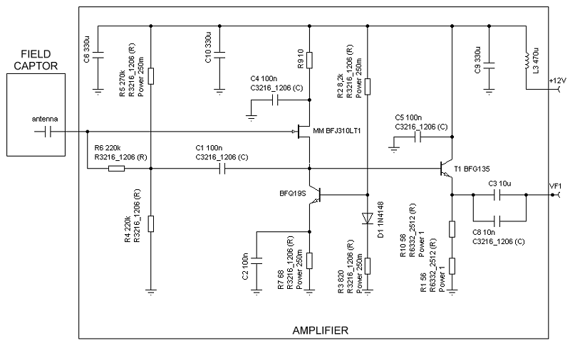
The active part of the antenna is composed by two stages:
• an high Z input buffer
• an high current line driver
The input device is a JFET, selected to have a low input capacitance and used in source follower configuration. While in theory this would be enought, there are few practical elements to consider, first of all the need to polarize the device and stabilize its operating point over a temperature range of -20 ° C and 60 ° C.
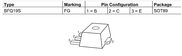
A simple solution that meets all the needs is the use of the bootstrap configuration, where a little bit of feedback is used to keep high the input impedance at radio frequencies, but at the same time allows us the use of medium-low resistance values for the control of the polarization of the gate. To work at its best, this configuration requires that the voltage gain of the follower is as close as possibile to the unity, performance mainly controlled by the source resistance. High values of such resistor however, require high supply voltages. The solution in this case, use a BFQ19S as dynamic load source. To the radio frequencies it present an high output impedance while for the continuous component, operates in the manner of a constant current generator, stabilized in temperature by the diode D1.
The output transistor, a BFG135, is polarized in a rigid manner from the previous stage and its load on the emitter. The quiescent current is about 60mA to ensure high linearity of the stage.
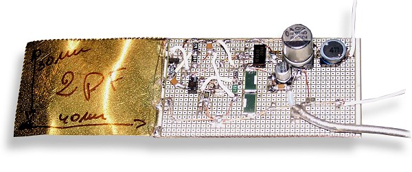
From theory to practice
The first prototype has found place on a trivial breadboard with the sensor made with a small cut of brass, size 30x40mm. In spite of the “rude” construction, the antenna is fully functional. For those wishing to replicate it, I recommend the development of a simple single-sided printed circuit board making sure to:
• R1, R10 and T1 become warm, so they need broad tracks on the PCB
• put C4 and C5 very close to the collectors of the respective devices (with a very short ground path of course) for a good filtering of the RF signals and to prevent undesirable phenomena of self-oscillation.
The test
Early laboratory tests substantially confirmed what defined in the design phase and verified in simulation. However, since the antenna is designed to operate for long periods, maybe on top of a pole exposed to the ice and the sun, I also performed some tests focused on its reliability.
 |
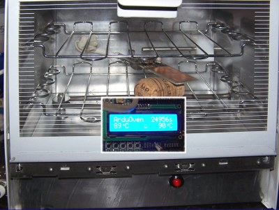 |
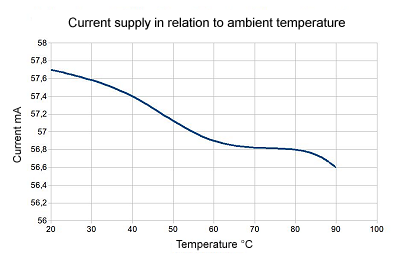
I put one of first samples on a small temperature controlled oven and I let it working for a series of 24-hour intervals, each one characterized by increasing temperature in steps of 20° C, up to a maximum of 80° C.
As synthetic parameter of the stability of the circuit and therefore of its ability to withstand high temperatures in reliable way, I chose the current consumption, getting the trend reported above.
At any temperature tested, the circuit remains very stable and there is no significant drift. The quiescent current from 20 to 80°C changes approximately 2% and this is an excellent result which also guarantees the stability of dynamic performance. I also successfully performed a test at 90°C of one hour, to simulate an "heat soak".
The fact that the currents remain stable against the temperature does not mean that the temperature has no effect on the lifespan of the components. The physics do not change and higher working temperature correspond to a shorter life. In particular the electrolytic capacitors could be the first component to fail. What we can instead say is that the failure will not occur in a sudden avalanche effect of some component.
An interesting comparison
At this point I guess, the reader will wonder how this antenna works with respect one of the most famous and popular, such as "mini whip" of PA0RDT.
On field reliable comparison are always difficult to achieve. What we can do instead is a simulation, placing the two antennas "in parallel" to receive the same signal as drawn below.
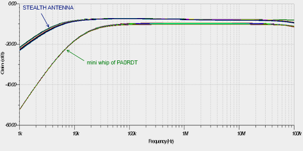
Let's see the result:
The group of curves on top, belong to the Stealth Antenna. How do we explain the slightly higher sensitivity (note: they were compared with the same effective height!) and the broader extension at lower frequencies?
These benefits comes from:
• probe with larger capacity (it is a little bigger)
• higher input impedance of the first stage
• minimized input capacitance
These are the key points.
Thus, with this antenna you can easily enjoy VLF listening, such as the SAQ transmissions, the radio-navigation Alpha coaster and some Ham experiments.
For those of you who want some more
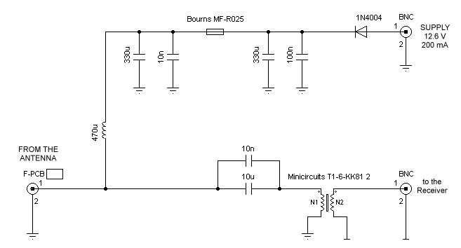
For those who find convenient feed the antenna through the coaxial cable, you can do so via the following circuit.
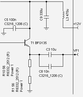 Detail of original version scheme |
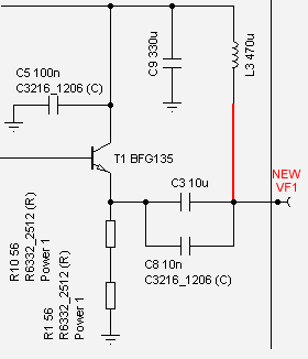 Here modified for remote power supply |
The proposed circuit also offers the following features:
• protection against reverse polarity by means of the protection diode (1N4004 or equivalent)
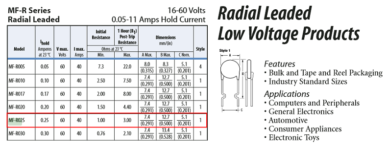
• protection against overloads and short circuits, by means the self-resettable fuse Bourns, MF-R05 which open the circuit as the current exceeds about 250mA.
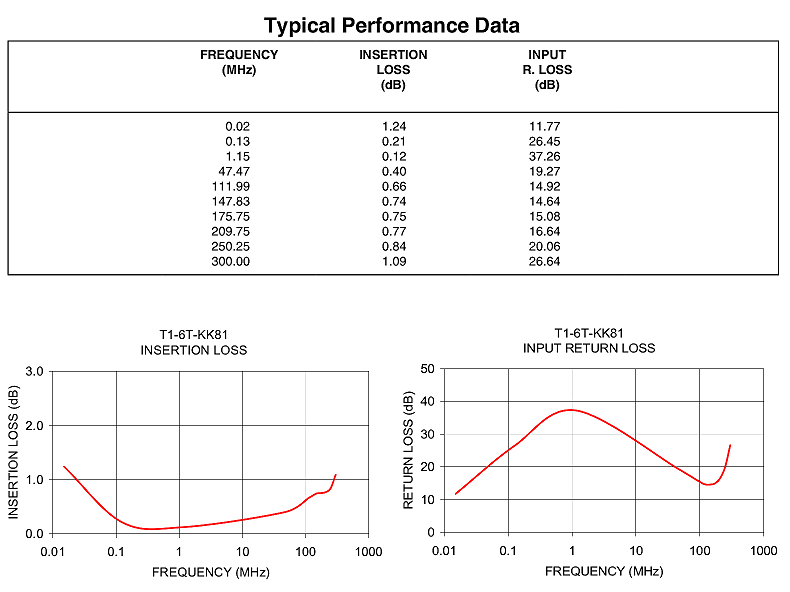
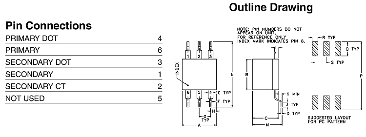
• Galvanic isolation of the antenna from the receiver through the transformer T1, Minicircuits model T1-6-KK-81. This device is specified for a very broad bandwidth ( 15kHz ~ 300MHz!), it has rather low insertion loss and handle strong signals. Last but not least : it is sold at a resonable price !
Of course, to employ this configuration you also need to change the antenna schematic as suggested on the previoust frame.
Conclusions
The antenna presented has proved simple and reliable replicability. Its cost is low and has the credentials to offer many years of honorable service.
Like all those of his family, is unfortunately very sensitive to electromagnetic pollution of anthropogenic nature and therefore should be placed as far as possible from obstacles, in open spaces.
I wish good VLF listening to everybody!
73, Pierluigi
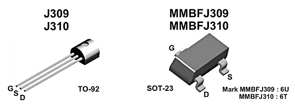
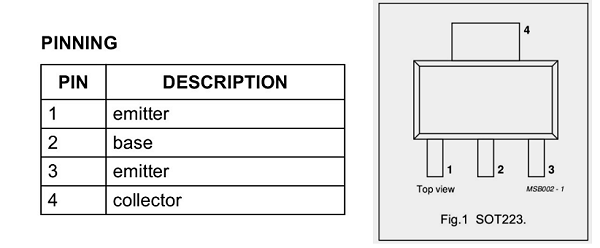
Appendix
In this chapter you can find some useful information to the use of the components and the Pin out.
 |
 |
Bibliography
- Pierluigi Poggi (2011), Antenne Attive, Sandit
- ARRL (1988). The ARRL Antenna Book. Newington, CT.: American Radio Relay League.
- Carr, Joseph J. (1994). "Small Loop Antennas for MW, AM BCB, LF and VLF Reception - Part 1." Elektor Electronics (UK), June 1994, pp. 58 – 63
- Carr, Joseph J. (1994). "Small Loop Antennas for MW, AM BCB, LF and VLF Reception - Part 2." Elektor Electronics (UK), July/August 1994, pp. 104 - 109.
- Carr, Joseph J. (1994). Joe Carr's Receiving Antenna Handbook.
- Kraus, John D. (1950). Antennas. New York: McGraw-Hill Book Co.
- Lankford, Dallas (1981). "Loop Antennas Theory and Practice." National Radio Club (USA). Reprint A-37.
- Nelson, Gordon P. (1965). "High Precision Direction Finding of
- Medium Wave Skywave Signals." National Radio Club (USA).
- Reprint A-1 (repeat number, different paper).
- Nelson, Gordon P. (n.d.). "The Vertical Pickup Pattern of the MW
- KRAUS, J.D.: ‘Antennas’ 2nd Ed. (McGraw-Hill Book Company) 0-07-100482-3, p. 251 (Section 6-8)
- John David Jackson, Classical Electrodynamics, 3rd edition (Wiley: New York, 1998)
- C.-A. Balanis, Antenna theory, analysis and design Wiley, 1997, capitolo 2.
- http://www.minicircuits.com
- http://www.bourns.com
- http://www.nxp.com
- http://www.infineon.com
- http://www.farchildsemi.com