At certain times of the day, one can detect on the electrical supply network the presence of signals whose frequency varies between 110Hz and 1600Hz. They are use for control different load function as: street lighting, tools and machines, water heating, special loads, shop windows, ventilations, storage heathers, summoning assistance, building lighting, pumping plants, domestic appliances, alerting, tariff changeover, air - conditioners and other special tasks.
This article will give you a little more information about them and how they are displayed on a spectrogram.
USED FREQUENCIES
From the VDEW, which is the main German Electricity
Company we have the following table about used frequencies :
| Frequence [Hz] | Bandspread [%] | Amplitude [%] |
| 110 | 1,7 | |
| 168 | -0,5...+0,5 | 1,7 |
| 175 | -0,5...+0,5 | 2,5 |
| 183,3 | -2...+1 | 3 |
| 190 | -0,5...+0,5 | 2,5 |
| 194 | 2 | |
| 206 | 2 | |
| 216,7 | -2...+1 | 3 |
| 228 | 2 | |
| 232 | -0,5...+0,5 | 1,7 |
| 267 | -0,5...+0,5 | 1,7 |
| 270 | 3 | |
| 283,3 | -2...+1 | 3 |
| 316,7 | -2...+1 | 3 |
| 383,3 | -2...+1 | 3 |
| 425 | -2...+1 | 3 |
| 485 | 4 | |
| 582 | 4 | |
| 600 | -2...+1 | 4 |
| 725 | 4 | |
| 750 | -2...+1 | 4 |
| 1050 | -2...+1 | 3 |
| 1350 | -2...+1 | 3 |
| 1600 | -2...+1 | 2,5 |
The bandspread indicates the allowable variation of the transmitter frequency upward and downard in percentage of their respective nominal frequency. The amplitude level is indicated in percent of the 50-Hz-main voltage. The odd frequency data originates from the time, when the audio frequency achievement was produced with mechanical converters. At this time, an engine activated an audio generator over the main wave. The number of pairs of poles of this generator amounts to a multiple opposite the propelling 50Hz machine. From that, the frequencies explain themselves as whole multiple, which were used before the introduction of the heavy current semiconductor technology. Thus e.g. a generator for 500 cycles per second has 10 times the pair of poles of its propelling engine.
The driving motors are partly synchronous engines, partly synchronous motors. Synchronous engines due to their slip never reach the nominal frequency. Thus the produced audio frequency cannot reach their nominal value at such plants. It was usual with such plants to indicate not the nominal frequency but the lowest frequency still permissible for the enterprise with a slip of 3%. Thus one spoke of the frequencies e.g. 194, 485, 582 and 725 cycles per second. The always varying load of the generator led also to a varying slip of the synchronous engine and thus again to a varying transmitter frequency. This is also the reason, why couplings for these frequencies are arranged as broadband filters.
The PULSADIS
system
 |
Since about thirty years, EDF (Electricité
de France) uses a system of remote control called PULSADIS which makes
it possible from the mains distribution centers to start the change of
tariff of the meters at the wanted hour, and optionally of other services
like the street lighting, etc. This system is based on the injection on
the mains of signals according to a code which the receivers recognize
and which gives them the order to carry out commutations corresponding
to the signals that they are supposed to recognize.
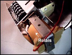
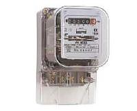
<< The relay actuated by the pulsadis system on an electric consumption counter |
The carrying signal is to 175 Hz with an amplitude minimum of 0,9% of the nominal voltage of the sector, that is to say 2,3V.
It is modulated by binary impulses according to
the following code:
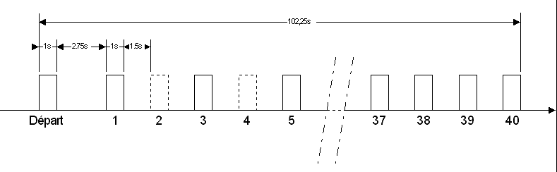
A signal of 1 second followed by a 2,75 seconds
silence indicates the beginning of screen. The receiver recognizes this
signal and starts to count time from this moment. The frame comprises 40
impulses of 2,5 seconds and its total duration is 102,25 seconds.
Each frame of pulse is composed of one duration of 1 second during which there can be or not emission of the 175 Hz carrier, and a 1,5 seconds silence being used as separator with the following frame. If the signal is present, it starts in the receivers a swing. Another impulse is designed to produce the opposite swing. If none of these two pulses are present, the receiver does not change its state. The pulses being associated per pairs (one starts, the other stops), 20 channels are available for all that types of different remote controls.
The diagram of figure 1 represents a standard frame. We show two missing pulses there, the 2nd and the 4rd.
The decoding of the screen thus requires to fulfill the following functions:
The detection with VLF system
The problem of the detection of the useful signal comes from its low amplitude (2% approximately, are -40 dB) compared to the nominal voltage of the sector, and the weak difference in frequency of the two signals:
Fsignal/Fpower = 175/50 = 3,5
Then a spectrogram analysis can help to detect an
to identify the signals nature.
They, can be detected directly from the electric
lines using a classical transformer with one or two coupling coils.
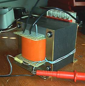
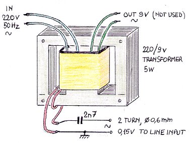
A simple and secure
Mains Power detector: practical realization and electric scheme
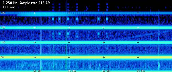
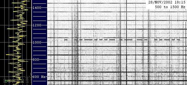
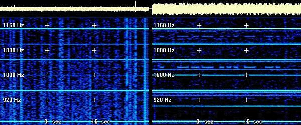
October 2003, 183 Hz
pulses analysed with Spectrogram, received in Belgium.
But those signals, using the electric network as antenna, can be received many distance from the origin place and with different reception antennas, as shows below:
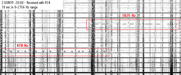
June 1999, Received
in Italy with RS4 receiver and 1m wip. Over the statics and 50 Hz harmonics,
two different signal at 470 Hz (with a dot of 125 mS) and 1025 Hz (with
a dot of 650 mS) are visible. The two signals, probably coming from two
different network, overlap for a short time.
18 June 1999, Received
in Italy with Marconi vertical antenna compared with a big loop placed
orizontally on the ground.
Strong and clear the 1024 Hz tone. With the loop the signal at 1024 Hz is much weaker but two harmonics at 1125 Hz and 825 Hz are visible. This particular one seems to come from Switzerland (more than 300 km from reception place in Italy).
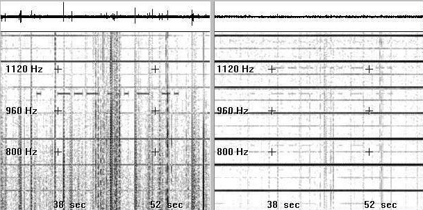
15 July 1999, 20:00
Marconi antenna compares with signals received with a transformer on the
electric line.
'On air' the signal at 1025 is not present, low harmonics of 50 Hz and good sferics are seen. On the mains the sferics are not present, harmonics are strong and the binary signal is clear with image at 1125 Hz. The result is different at different time: two hours before the situation at 1025 Hz was opposite.
Injection of signal on the mains and emissions control
A typical structure of one ripple control system consists of a control programming unit, remote control facilities between control centre and substations and many receivers in the low - voltage distribution network.
Here below an example with a Trasmitter, a serial coupling and an "home receiver"
![]()
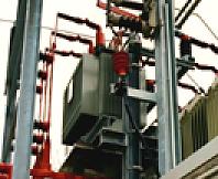
The signal injection levels usually takes place at the medium - voltage level (10, 20 or 35 kV) symmetrically, in all three phases, so that propagation can penetrate right down to the low voltage level. But it can operate at any voltage level between 0,4 and 110 kV. The choice of injection level depends mainly on the size of the network to be controlled as well as the type of network ( rural or municipal ).
System can be designed for parallel or series injection
of audio frequency in the network. In the case of parallel injection, impedances
of high voltage network and that of power transformer are in parallel with
impedances of the network to be controlled. When series injection is applied,
the both networks are connected in series and impedances of the power transformer
and high voltage network must be much lower than that of the network to
be controlled.
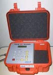 |
Here beside a "PULSE TRACKER" device, used for
network maintenance and control. . It enables supervision and analysis
of the telegrams quality from 160 to 500 Hz (Pulsadis 40/50, Semagyr
50a/50b/52/56, Versacom or Customized) either locally or from a distant
location.
This device records and analyses all characteristics: rate, offset, width and interfering pulses and enables detailed recording of 175Hz telegrams corresponding to the pre-set. tariffs. It enables setting detection and supervision thresholds locally or remotely ans identifies the different faults for each single order. |
REFERENCES
More details about this argument can be found at:
http://www.scle-france.com/ang/produits/gestion-energie/controleur/produits/pulse.htm
http://www.elstermetering.com/en/796.shtml
http://www.actaris.com/elect/lmtrans.shtml
http://www.tel.hr/hdc-itd/Engleski/RCS.htm#Choice%20of%20control%20frequency