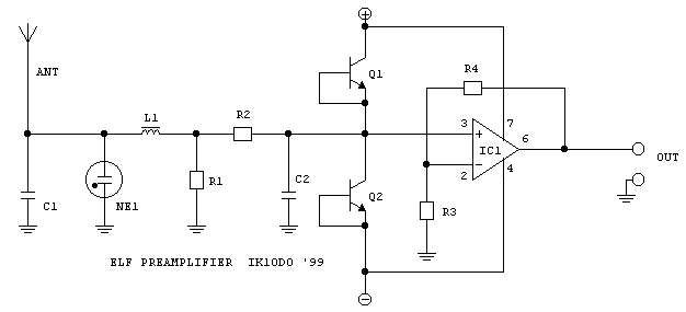
CIRCUIT DESCRIPTION
The antenna is usually a wire, as high as you can.
In my case it is a Marconi-tee, designed for 137 kHz band amateur operations.
It is a vertical wire of about 13m, with a top hat composed by three
parallel wires, spaced 1m, long 24m. The total capacitance of the antenna
to ground is about 350pF. The antenna is very well insulated with ceramic
insulators.
The preamplifier is connected by means of a coaxial
cable. At these frequencies the cable may be seen as a simple capacitor,
of about 90pF/m (for a 50? cable). This capacitance is represented as C1
in the schematics; in my case it is about 1800pF (20m cable).
The first element of the preamplifier is a small
neon pilot lamp (without resistor). The neon lamp is used as transient
limiter, lighting when the DC voltage in antenna exceedes 120V or so. The
lamp lights often during thunderstorms be careful, high wires may be
dangerous structures
Then a small inductance stops RF signals, avoiding
demodulation of local MF stations. R1 is an high valued resistor, usually
several Mohm. It serves as DC return for op-amp bias and antenna (static)
currents. R1 is in parallel with the input capacitance, and sets the LF
corner (-3dB point) of the amplifier; in my case the LF rollover is at
about 5Hz.
R2 and C2 set the HF corner of the amplifier; I
use 100 kohm and 500pF for a 3 kHz cut. If you need 30kHz band use 33kohm
and 150pF.
Q1 and Q2 work as low-leakage clipping diodes.
Usual diodes in glass envelope, like the common 1N4148, may have quite
high leakage currents; the B-C junction of a signal transistor is superior
in this aspect. In case the input voltage increases over +/- 15V the diodes
conduct, avoiding destruction of the op-amp.
The operational amplifier is an OP07, manufactured
by Analog Devices, Burr Brown, and probably others. It has very good noise
and dynamic characteristics, and a very low leakage current. It costs about
$3 in small quantities. Mount it on a socket
and buy more than one, it
may decide to break down in extreme conditions (thunderstorms).
The voltage gain of the op-amp is set by R3 and
R4. In my case it is 100 (100ohm and 10kohm). You may wish to replace R3
with a 10kohm potentiometer with a 10ohm resistor in series, and have a
variable gain to adapt to the input sensitivity of the following circuits
(SoundBlaster, DAT, etc.).
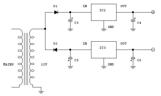
The power supply is very simple. I use mains power,
but for portable/remote operations some batteries in series are OK the
OP07 only drains a few mA. In this case omit the regulators; C4 and C6
should be at least 100 µF, and mounted close to the op-amp.
COMPONENT LIST - VALUES ARE INDICATIVE (SEE TEXT)
| R1: | 10 Mohm | L1: | 10 µH moulded inductor | |
| R2: | 100 kohm | NE1: | Neon bulb, without series resistor | |
| R3: | 100 ohm | D1-D2: | 1N4002 or similar | |
| R4: | 10 kohm | Q1-Q2: | BC237B, BC108B, BC107, 2N3904 (NPN) | |
| C1: | see text (cable capacitance) | IC1: | OP07 | |
| C2: | 470 pF | IC2: | 78L15 | |
| C3: | 100 µF 25V electrolytic | IC3: | 79L15 | |
| C4: | 10 µF 25V electrolytic | Transf. Primary: | mains voltage (230V or 115V, dep. on your country) | |
| C5: | 100 µF 25V electrolytic | Transf. Secundary: | 12V, 100 mA min. | |
| C6: | 10 µF 25V electrolytic |
TESTING, USING,
TUNING, MODIFYING.
By first, you need an antenna. Try to keep the
wire vertical and away from obstacles, trees, buildings. Bring the signal
to your station by a coaxial cable. Connect the braid of the cable to a
good earth (water pipe, ground stack), possibly separated from your mains
earth. The system is VERY small respect to the wavelengths in use (100
km at 3 kHz, 30000 km at 10 Hz!), so it is not important what side of the
braid is actually connected to the earth.
Leave the antenna disconnected, connect an oscilloscope
or at least a voltmeter to the op-amp output and monitor the voltage. It
should be 0V +/- 500mV. Now connect the antenna the voltage should start
to fluctuate, and probably a 50Hz (well, 60Hz outside Europe) component
will show up. It should be three volt peak-to-peak maximum (1Veff if you
use the volmeter). If the 50 Hz component exceedes this value you will
need to decrease the gain (increase R3).
If the AC component is low but the DC drives the
op-amp in saturation you may lower R1, down to 1Mohm or so. If the DC component
is still a problem you have to add a capacitor in series with R2 (10nF
or so) and a resistor in parallel to C2 (1Mohm); in this case also the
lower part of the spectrum will be very attenuated. You may also consider
using a smaller antenna.
The mains signal and relative harmonics are usually
the limiting factor for ELF weak signal listening. There are two ways to
suppress it: notch filters and low pass filters. A notch is a filter that
suppresses a single frequency. It has to be tuned to the mains frequency.
Many designs are available; I will publish some experiments with notch
filters later. Currently I use a professional variable filter (KEMO VBF/8
at 48 dB/octave), cutting from 45Hz up. This setup is excellent to monitor
Schumann resonances. Renato IK1QFK instead added a capacitor in parallel
with R4, building an integrator. He has a roll-off starting at 10 Hz, and
the 50 Hz is suppressed by about 15 dB. You must experiment with Spectrogram
and look for the best S/N ratio of the Schumann resonances; or leave the
civilization and listen at some km from the mains grid.
CONCLUSIONS
A preamplifier has been descripted for ELF/ULF
monitoring. The preamplifier has protection for atmospheric discharges,
and low noise properties. It may be used as-is or adapted to different
listening situations.
Marco Bruno IK1ODO Dec.,
1999