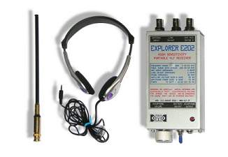
If you are looking for a small receiver, simple to build, which runs on batteries, which works with a small antenna, which works with headphones, which also provides a good signal for PC analysis... the Explorer E202 meets all these needs.
Since this project is meant for beginners there are also included in the article some basic concepts: they are also mentioned in other articles on the site so If you already know these things just jump to the next paragraph.
A
brief introduction about this project
This project is a receiver for base
band radio signals using direct reception without
frequency conversion. The frequency range from few Hz to
beyond 10 kHz makes it suitable to receive radio signals
of natural origin; signals not generated by human
activity but by physical phenomena such as lightning and
solar storms. Received signals are heard directly in
your headset. The receiver amplifies the electric
component of an electromagnetic signal.
 |
 |
It can be assembled as a compact,
lightweight and extremely sensitive receiver. It
functions well in the field thanks to an internal
battery with autonomy of 40 hours. It will also function
as a base station receiver using external power in a
permanent monitoring observatory.
HOW
DOES THE E202 WORK?
The diagram of the receiver consists
of two active stages with supply input protection and
regulation plus a stable opamp (7809) bias supply. The
TLE2426 is a “virtual ground generator”: it supplies the
V/2 for the TL071 with a very low-impedance 7 milliOhm
output.
The input has two stages of
over-voltage protection and sets the input impedance at
5 Mohm. The first stage has non-inverting 30 db gain and
converts the antenna input to a medium impedance output
with level suitable for a LINE input to a PC or a
portable recorder. The first stage is protected against
voltage surges and has low current noise which makes the
receiver sensitive to weak signals even with short
antennas. The antenna is galvanically decoupled from the
first stage: this prevents the static electric field
from saturating the receiver during a lightning storm or
when the receiver is in motion; for example during a
walk.
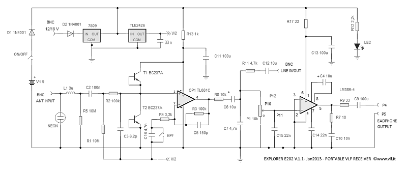
For a full dimension scheme
click here.
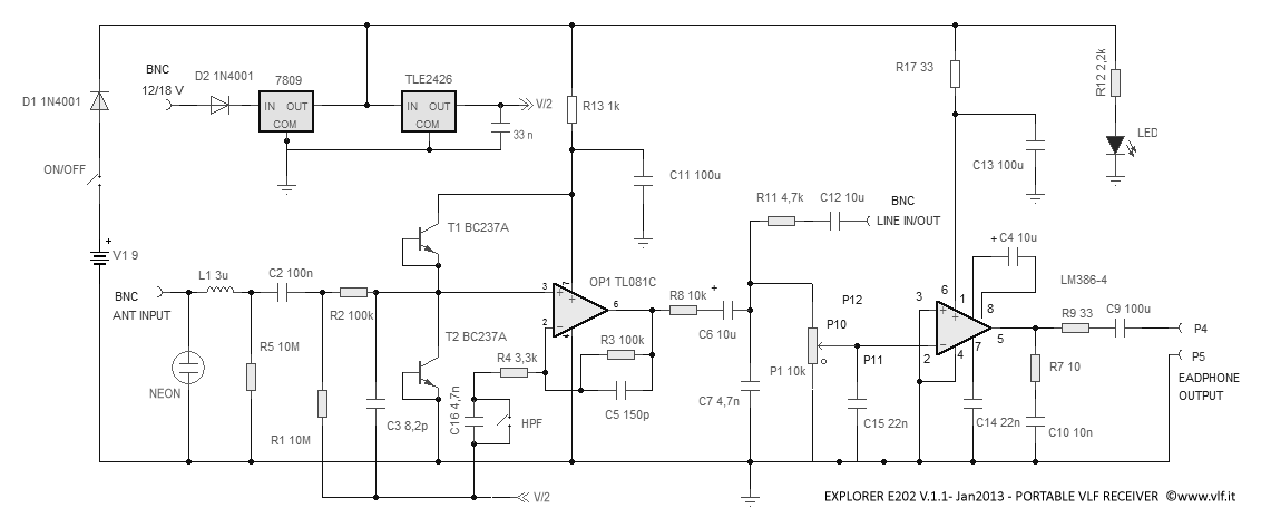
The second stage consists of a low
impedance amplifier (LM386-4) to drive a headset which
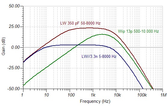
is perfect for “live” field listening. The jump HPF
short-circuits a capacitor that acts as a high-pass
filter. Removing the jumper between pins 6 and 7
activates a high-pass filter that attenuates low
frequencies such as 50 Hz by about 30 dB. You can build
it as a jumper on the board or as an external switch on
the receiver box.
In the graph the frequency response of
the receiver with a whip antenna: with (brown curve) and
without high pass filter jumper (green curve).
TECHNICAL SPECIFICATIONS
- Frequency range with a simple 75 cm stylus: 120 Hz - 10 kHz, +/- 3 dB
- Frequency range with low impedance source: 3 Hz – 10 kHz, +/- 3 dB
- Sensitivity: 1 µV/m in 1 Hz RBW @ 1 kHz using 75 cm telescopic stylus
- Internal power supply: 9V transistor battery, lasts about 40 hours
- External power supply: 12 to 18 Vcc (20 mA)
- Protected against battery polarity reversal
- Protected against external power supply polarity reversal
- Headphone output: 33 Ohm impedance (good for most walkman type headsets)
- LINE connector with double function: Line output for PC or Recorder and can also be used as an audio input to amplify an audio signal and listen with the headphones
- Antenna input: 5 Mohm impedance.
RECEIVER
CHARACTERISTICS
The receiver frequency response is
strongly influenced by the type of antenna used. This is
because, due to the low frequencies involved and the
high input impedance, the antenna does not behave as an
antenna itself but as a field probe. It could not be
otherwise: a real antenna for 1 kHz frequency should be
75 km high.
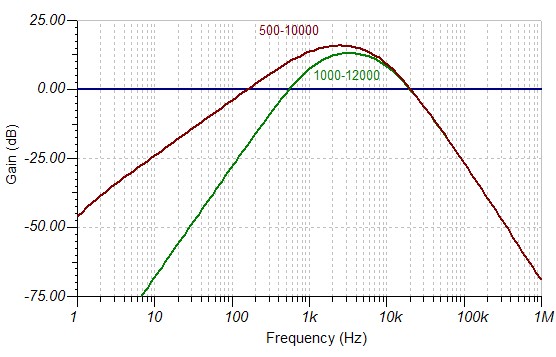
The graph, which is purely indicative
shows varied frequency responses. Represented here are
the curves of gain between the voltage detected by the
antenna and the output voltage to the LINE output jack
of the receiver with three different antennas:
Green curve: telescopic antenna
directly on the receiver
Brown curve: 45 m long wire antenna
(350 pF equivalent) directly connected to the receiver
Blue curve: the same long wire
connected to the receiver by 30 m of RG58 cable. The
gain is significantly reduced to the advantage of
linearity at low frequencies
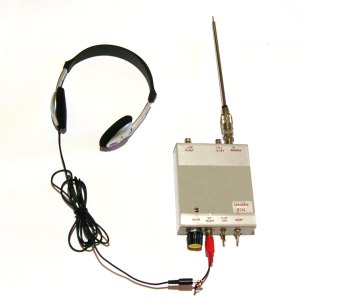
RECEIVER
CONNECTIONS
On the scheme is suggested the use of
three BNCf sockets:
one for the connection of the stylus
or a wire antenna
one for the output signal to be sent
to line input of a recorder or a PC
one for an external power supply: from
12 to 18 V thus compatible with power taken from a car
cigarette lighter.
They provide a good and stable
mechanical and electrical connection, also where the
receiver is used as a base receiver for unattended
monitoring station, and reliability is an important
requirement.
The headset connection can be a
standard 3.5 mm stereo jack, so you can use the receiver
with a standard player headset (connect the L and R
channel together, in parallel).
The circuit must be enclosed in a
metal box, and the metal box itself must be connected to
circuit ground. It is essential for proper working of
this receiver.
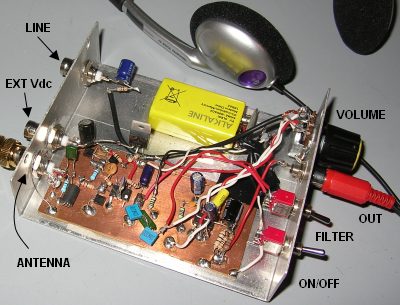
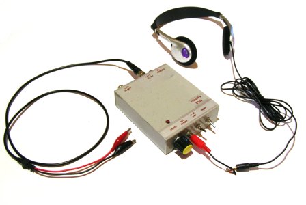
One way to build the E202 Receiver.
POWER
SUPPLY
The receiver can be powered by an
internal 9 V battery or by an external voltage between
12 and 18 V supplied from a source like a portable
battery or a motor vehicle. The external voltage is
internally stabilized by a 7809 IC before being used by
the circuit to minimize the influence of noise on
reception. Both connections are protected against
reverse polarity. Current drain at a medium volume
setting is 10 mA. It ensures autonomy of more than 40
continuous hours with a standard 9 V alkaline battery.
The receiver operates from 18 V down to 6 V: below this
voltage the signal may sound distorted and the input
stage overloading with interfering signals like telex
and other types of RF signals. Under these conditions
simply replace the battery.
VOLUME
REGULATION
The circuit has only one control: the
headphone volume. The receiver is broadband and without
conversion so you do not need the tuning operations that
take place in an ordinary radio. Volume is adjusted by a
potentiometer on the bottom of the receiver. The volume
control on the headphone cable must always remain at
maximum. When located near power lines the volume in the
headphones may be extremely loud so use this precaution:
before you switch on the receiver, put the volume to
zero. Turn the receiver on and then gradually turn up
the volume. When using the receiver connected to a PC or
recorder via the LINE output, once setup is optimized,
set the volume control to minimum if not using the
headset.
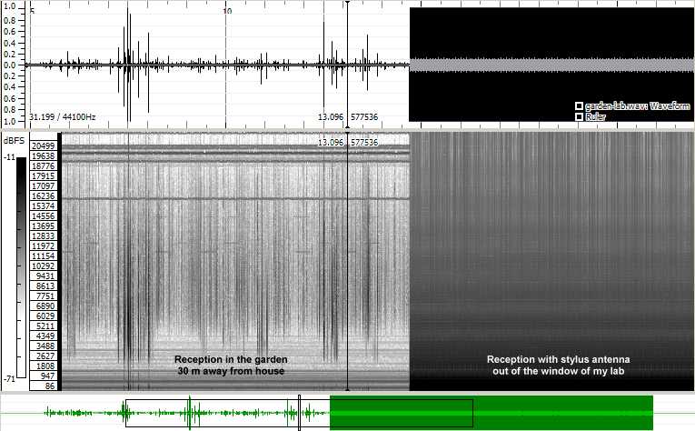
STYLUS
ANTENNA AND GROUND REFERENCE
The receiver operates by sensing the
potential difference between stylus antenna and a ground
reference; the latter consisting of the operator's body
touching the metal box of the receiver. Raising the
receiver higher above ground provides more signal. The
reference ground is also essential for the correct
operation of the receiver, so if you do not hold the
receiver by hand it is necessary that the receiver is
connected to an Earth ground. For example if the
receiver is placed on a tripod the impedance of the
stylus is very high, so even a simple carpenter's nail,
stuck ten cm in moist soil acts as a near-perfect
ground. The whip antenna should be connected directly to
the receiver antenna jack without connecting cables.
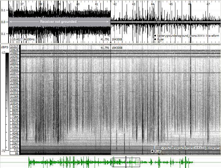
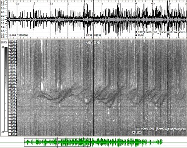
In the picture above is a signal
received in my garden with the E202 and 75 cm stylus,
without and with receiver connected to ground. Left part
without ground connection and Right part with it on. The
ground connection reduces the hum noise by 20 dB. Signal
processed with Sonic Visualizer software.
EXPLORER
E202 WITH WIRE ANTENNA
Although the project was designed to
work with short and portable antennas, the receiver
works very well with long wire antennas too. Large wire
antennas extend the sensitivity especially at very low
frequencies, allowing reception of Schumann resonances
and 82 Hz signals of Zevs network (direct to submerged
submarines). With the wire antenna you may use a coaxial
cable connection between antenna and receiver. The
length should not exceed one third of the length of the
antenna. The coaxial cable at VLF behaves essentially
like a capacitor: that coupled with the wire antenna
capacity, acts as a divider, reducing the signal.
A meter of RG58 connected to a 1m
stylus loses 99% signal power strength, reducing the
reception by 20 dB. A wire antenna of 15 meters, for
example, can tolerate a cable to the receiver of 5
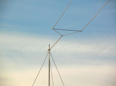
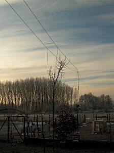
meters length. The picture below is a winter view of my
Marconi antenna with dual capacitive hat: the antenna is
11 meters high and is 45 meters long.
 |
 |
Electrically the Marconi antenna is
nothing more than a vertical antenna with a tip that
splits and goes horizontally, making a hat. This
configuration gives great performance on low
frequencies, and for this reason it is also widely used
by the military to transmit signals in the VLF band.
The dimensions are not critical
because the antenna is not resonant: 3 meters vertical
and 6 meters horizontal are sufficient to provide a
large increase in efficiency compared to a 75 cm stylus;
especially in the reception of frequencies below 100 Hz.
The figure above shows how a
horizontal dipole behaves at VLF frequencies. The
receiver is not differential but referred to ground, so
the received component will always be the vertical one,
even with the antenna placed horizontally. This is
because the antenna is much shorter than the signal
wavelength and therefore does not behave as an antenna
but as a field probe. It detects the vertical voltage
between two points: the ground and the antenna.
The use of large wire antennas usually
reduces the effect of hum noise by increasing the SN
ratio: especially when compared to a stylus placed in
the same position. Set up in a backyard or a garden next
to a house they can be an excellent solution with
greatly improved SN ratio.
THE
SHIELDING
Not all places provide good reception.
When available, open spaces are ideal locations: away
from structures that will bring the ground point as high
as buildings, trees or metal masses.
To view the limits on VLF reception
you can imagine that the structures create shadows.
In a park with trees, behind a wall,
in a cave the electric field is zero, and the VLF
receiver will not receive anything.
Same is true for a balcony, a room in
an apartment, a courtyard surrounded by walls: they are
not compatible sites to receive VLF signals.
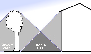
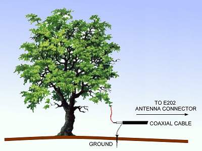
THE
TREE THAT WORKS AS AN ANTENNA
No, it is not a legend: a tree can
really work as antenna.
For the reasons stated above under a
tree you do not receive VLF signals. The plant with its
high water content is conductive, so it carries the
ground plane up to its peak. Within a forest, the
receiver is almost completely silent. But the tree can
be used as an antenna with some success, mostly due to
its size and height. To use the tree as an antenna
connect the hot antenna lead to a screw fastened into
the trunk or a limb as high as possible. Then connect
the antenna cold pole to ground at the tree’s
base. In case of Electrical Storms immediately
disconnect the receiver from the tree.
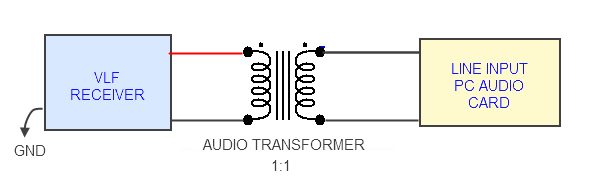
GALVANIC
ISOLATION
Reception starts with simple play,
but, after a while comes the need to acquire signals to
study and analyze them. We must therefore have a
suitable recording device. The sound card of a PC is an
excellent way to good quality and low cost recording to
readily analyze signals from a receiver. The computer,
however, may be the source of signals in the VLF band,
which can interfere with the reception of natural radio
signals. The computer and receiver must therefore need
to be placed as far apart as possible and the receiver
must be connected to an earth ground as well. This
sometimes may not be enough because the noise can also
propagate through the cable connecting the PC to the
receiver. It is difficult to quantify this trouble
because it varies from PC to PC, but it is easy to check
with the headset: if connecting the cable to the PC LINE
the receiver suddenly becomes noisy, it means that the
PC is inducing noise to the receiver. It is necessary,
in this case to isolate the signal line, interrupting
the metal continuity. This requires the use of a 1:1,
600 ohm audio transformer, to connect the receiver to
the PC with galvanic isolation.
HUM
NOISE
In addition to the shielding effect,
it is necessary to move away as far as possible from the
signal emitted from the mains at 50/60 Hz: switching
power supplies, electric engines, televisions,
computers... with their emissions completely obscure the
natural radio signal. Just think that in your home the
level of hum is 120 dB higher than natural radio
signals: one million times greater in voltage!
In urban areas it is therefore very
difficult to find appropriate locations, while in the
open countryside away from the power lines hum noise
disappears allowing excellent of reception of natural
radio signals.
MICROPHONIC
EFFECT
The Stylus produces a microphonic
effect: it behaves like a microphone: at times motion of
the receiver/antenna gives the impression of listening
to a microphone input instead of an antenna. It is said
in these situations that you "hear the wind". This is
not a fault of the receiver but it is the direct effect
of how electric field receivers work: the whip antenna
works very similar in fact to a condenser microphone.
This happens whether we are moving with the receiver in
hand or whether it is the wind vibrating the antenna. In
a permanent observing station this problem is minimized
by using large wire antennas, very stretched, or tens of
kilograms heavy antennas so that they are mechanically
stable.
FALSE
SIGNALS
Walking with the receiver in hand it
is possible to hear other types of signals. Synthetic
clothing, during movement, emit small electrostatic
discharges that are detected by the receiver: the same
phenomenon that produces the sparkle of pajamas in the
dark. The gravel courtyard or street, stepped on, may
emit piezo-electric signals that you hear with the
receiver headphones and is very similar to the sound of
gravel under your shoes, only much stronger. Small
insects, fluttering their wings near the antenna
modulate the earth's static field: a signal similar to
the hum of their wings can be heard clearly in the
headphones.
USE
OF THE PORTABLE RECEIVER DURING STORMS
The circuit input is protected from
transient voltage and can withstand shocks of several
thousand volts without damage. It is not recommended for
reasons of safety to use it when the weather is bad: If
during a walk in the mountains storm clouds are
gathering over your head it is not appropriate to
continue with reception.
For the same reason we should not seek
shelter under a tree, or handle sharp metal objects:
Do not use the portable receiver
outdoors during a thunderstorm!!!
 |
 |
Two pictures, taken from my garden
during a stormy afternoon.
PERMANENT
VLF OBSERVATIONS DURING STORMS
Where the wire antenna is external and
the receiver is inside the risks are lower for the
circuit: the input stages are well protected so
relatively close lightning usually will not damage the
receiver. The probability of damage is more or less
similar to a common radio receiver connected to the
antenna. The use of this receiver at fixed locations for
long periods of time revealed substantial protection
even with discharges within a few hundred meters away.
If the location is uninhabited it is advisable to unplug
the receiver from the PC, to avoid a surge from damaging
the computer's sound card. However, avoid touching the
equipment: good sense suggests that with a storm in
progress is not very healthy handling equipment
connected to an external antenna.
USING
THE RECEIVER AS AN AUDIO MONITOR
The line output can also be used as
input. Disconnect the antenna and connect a BNC coaxial
cable with alligator clips to the LINE output jack. A
signal introduced this way will be heard in the
headphones. If more gain is needed move the
BNC/alligator cable to the Antenna input jack. The LINE
input offers a medium impedance with up to 40 dB gain to
the headset: this lets you use the receiver as an audio
tester to verify your VLF installation. For example in a
monitoring station, where you have several receivers
installed, a quick check with headphones will allow you
to determine which signal lines are working properly and
which are not, without the help of computers.
A second application of the receiver
as a testing instrument is through the use of an
oscilloscope probe connected to the antenna input. The
signal can be extracted from the LINE output to be
placed directly into the sound card: in this case the
amplification is fixed and the PC can function as an
audio band oscilloscope. Simultaneously, the detected
signal can be heard in the headphones, setting the
volume control to adjust the level. A convenient audio
signal tester to determine what is working in any type
of audio circuit.
SIGNAL
ANALYSIS:
THE SPECTROGRAM
The spectrogram is a graphical
representation of the signal and shows how the
frequencies evolve in time. The spectrogram provides
great help for studying and identifying the source of
the received signals. There are several free programs
that perform this function. Among the most popular there
are:
- SpectrumLab, http://www.qsl.net/dl4yhf/. The most complete, but, complex to use: it is the arrival point.
- Spectran, http://www.weaksignals.com, more limited but easy to use: good to start with.
- Sonic Visualizer http://www.sonicvisualiser.org/ Not useful for real-time analysis but very good for wave files, post processing and representation.
WHAT
YOU HEAR AND WHAT YOU CAN'T HEAR
If we have found a place outside and
away from power lines, signals present 24 hours a day
are statics: similar to the sound of dust on the old
vinyl disks, they provide a constant crackle.
These are the signals radiated by
lightning strikes that fall within a few thousand miles
from the listening position. They are the first
test indication that the receiver is alive and working.
At night the propagation phenomena distort these signals
causing effects similar to twittering: these signals are
called “tweeks”. In periods of strong solar activity
some other phenomena can occur such as Whistlers and
Chorus.
Many signals cannot be heard, but only
appear in spectrograms due to being either lower or
higher in frequency than the range of our hearing. Here
is a sample reception below 100 Hz:
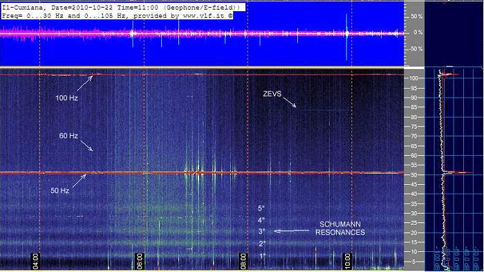
In the spectrogram above, developed
with SpectrumLab and obtained on a received signal with
a Marconi wire antenna, are visible: the Schumann
resonances, a 82 Hz Zevs signal from a Russian submarine
broadcast network, 50 Hz network, the first harmonic at
100 Hz and the weak 60 Hz signal of American power grid.
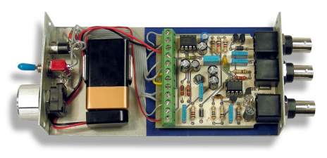
COMPONENTS AVAILABILITY
The receiver is simple and components are easy to find in any electronics shop, or from international distributors by purchasing on their web sites. Here below a more serious realization with the use of a specific printed circuit.
REFERENCES
For a more complete description of VLF
signals refer to the Book: RADIO
NATURE and also listen to examples posted on www.vlf.it, in the
"Signals Galleries".
Many thanks to Dave Ewer for the
English revision.
Return to www.vlf.it main index