by Sven Nordin SM5LE
After two years of searching for Schumann resonances, both in- and outdoor, all attempts resulted in no substantial reception. The indoor reception failed because of house acoustic resonances and 230 V AC noise. False Schumann look-alikes was the only result. Outdoor was the usual problems, acoustics from highways, wind, rain, nearby job activities etc.
So as a last attempt I said “Why not test underground?”. At first I measured 230V AC “earth currents” with a stick in the ground to find 230 V AC minima in the garden. And then I started to dig a 1.5 m deep hole ...
This article describes the equipment being used and the measured results.
Technical Description
Block Diagram
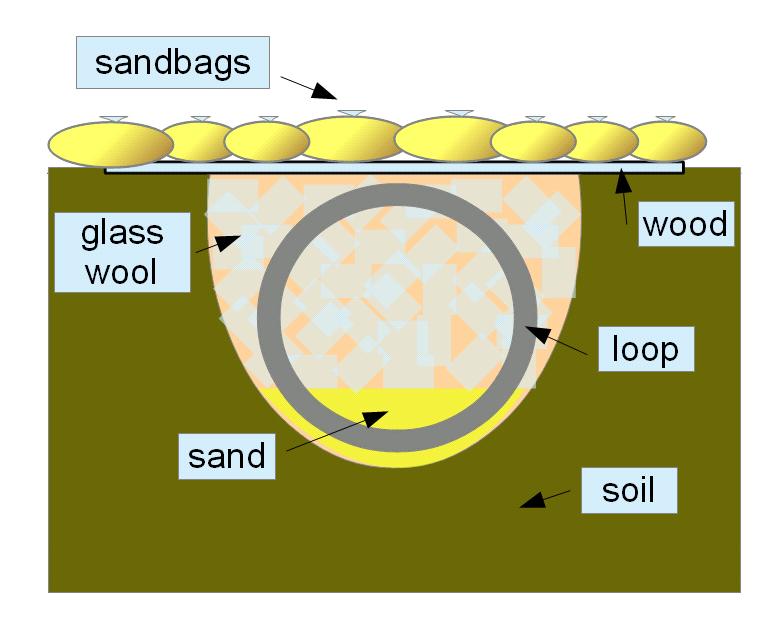
Loop – Initially made for indoor use on a wood frame. The loop is modified to function reasonable outdoor in the ground. It is isolated with volcano tape and also with some layer of plastic and glass wool. There is also a single shield layer, made of aluminium foil. The foil is connected to equipment ground. The loop is center tapped. It consist of 2x1500 turns of 0.2 mm Cu wire, in total a resistance of 7860 ohm. The loop diameter is 1.2 m and total wire length is approx. 11 km.
Preamp – Is the op amp INA114 . The circuit diagram is taken from the data- application sheet.
http://www.ti.com/lit/ds/symlink/ina114.pdf
DC-offset op amp OP27 - Is used for adjusting the preamp DC output level to fit the VCO (Voltage Controlled Oscillator) input. The output level from preamp is 0 V, if the loop is symmetric. The output level to the VCO shall be +3 V. The 0 V is adjusted to +3 V level by the 25k trim potentiometer on the DC-offset op amp. The adjustment also changes the VCO frequency.
Data sheet http://www.analog.com/static/imported-files/data_sheets/OP27.pdf
VCO XR2206 - Frequency is set somewhere in the range 500 -700 Hz by the 100k potentiometer. See circuit diagram. The frequency is choosed as to lay in middle of ordinary speech/music audio range. Then the VCO signal is fed to the FM transmitter.
The VCO XR2206 from EXAR is available in kit form from http://www.electrokit.com/ in Sweden. The kit is called “sinusgenerator”. It should be observed that the input (pin 7, that change the frequency) is current driven. 3.9 k ohm has to be put in series to avoid to much input current.
The XR2206 seems to have very good 1/f noise.
Data sheet, available on Internet. https://www.sparkfun.com/products/retired/10015
FM transmitter - A very low power transmitter for cordless audio connection use between an iPhone and a car FM radio. The FM deviation is set to ca. 30 kHz by the VCO output potentiometer. The transmitter is battery operated and the current consumption is very low. The supply voltage is 3 V and should be well stabilized. No license is needed in Sweden for this type of transmitter. The receive distance is about 10 m, enough to isolate from house AC mains etc..
FM receiver – An ordinary consumer FM broadcast receiver is connected to the A/D converter.
A/D converter E-MU 0202 – The FM radio audio output is connected to the A/D converter. One advantage for using FM/FM is that the A/D converter does not need to go down to 7.8 Hz. It needs only to handle a tone somewhere in the 500-700 Hz range. A FM/FM system is rather good and robust for a transmitting/receiving link system.
Spectrum Lab - A freeware program. The VCO output is FM-modulated with Schumann resonances and are demodulated by Spectrum Lab FM demodulator.
Not included in the block diagram is the outdoor power supply, which is a car battery with a solar panel and a DC/DC converter +/- 15 V.
Ground Cross-section
The loop is buried in north/south direction. The top of the loop is ca. 20 cm below ground surface.
Measurement Examples
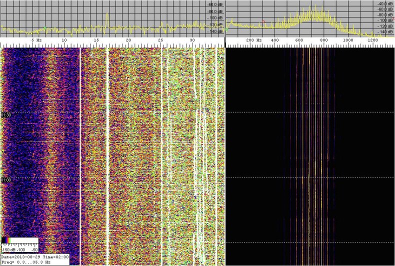
Waterfall - Night Measurement
(Time is UTC)
From left:
- 0 to 2 Hz: Noise, mostly from equipment.
- First Schumann resonance at 7.8 Hz
- 12.5 Hz is 50 Hz/4
- 14 Hz is second Schumann resonance
- 16 2/3 Hz from local commuter train
- 20 Hz is third Schumann resonance
- 25 Hz is 50 Hz /2
- 25 Hz and up is noise from 230 V AC and some Schumann resonance
The spectra to the right in the waterfall emanates from the received FM modulated 700 Hz signal.
Frequency and Amplitude Plot
Schumann resonance frequencies 1, 2, and 3 are added and then divided by 3. The frequency scale is relative. The lower green plot shows amplitude. Horizontal scale length is 36 h (1 1/2 days).
Reception Environment
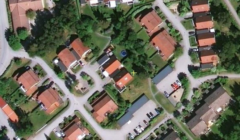
The garden, where the loop is placed, is in a typical residential area, 20 km south of Stockholm. Height above sea level is 40 meter. Location coordinates are N 59.1827236 deg and E 18.1510906 deg and QTH locator is JO99bd.
In less than 2 km radius are a commuter train station, bus stations, highways, a 10 MW gas turbine power station, substation, surrounding houses with their own heating equipment, ADSL telephone lines, coaxial cable-TV, etc..
Houses mains supply are both 3-phase and single phase 230 V AC. Unbalance and unlinearity in the main cause subharmonics, 50 Hz divided by 2, 3, 4, 5 etc..
It is amazing that Schumann resonances can be received at all. Even if the resonances are weaker during night time, the reception is better that time. Rain and wind does not affect the reception.
Picture shows the house and loop position (yellow cross) and surrounding houses.
Circuit Diagrams
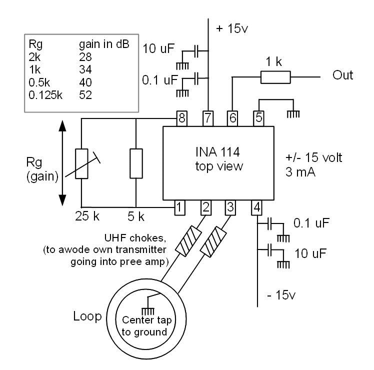
Preamplifier INA114
Tuning tip: A lot of gain is needed to pick up the 1pT Schumann resonance, but to much gain will cause oscillation. Start with 30-40 dB.
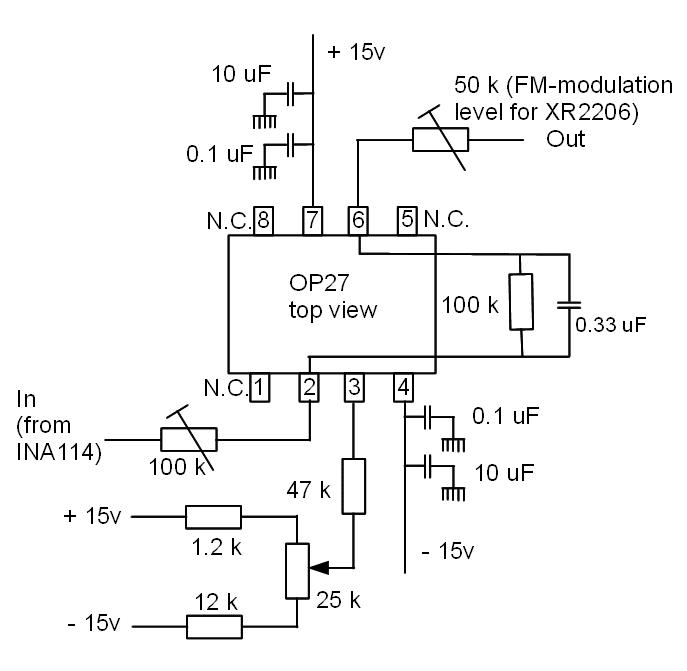
DC-Offset Op Amp OP27.
Tuning tip: With the 100k potentiometer gain can be set. Together with the preamp something like 60 dB is needed. However if one have very strong spuriouses (mostly 50 Hz) to much gain can cause limitation and noise. The 0.33 uF act as a LP filter.
The 25k potentiometer sets the offset. It should be set so that the VCO generates an audio tone somewhere between 500 to 700 Hz. Look on the Spectrum Lab screen for spuriouses generated by the A/D converter and PC. Avoid those spurious frequencies.
The output 50k potentiometer sets the VCO FM deviation. Use Spectrum Lab screen to set the deviation to ca. +/- 50 Hz. The FM detection bandwidth should be in that order in Spectrum Lab. To much deviation causes distortion and noise.
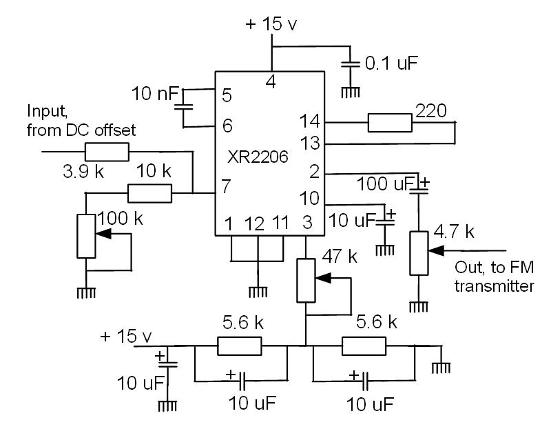
VCO XR 2206
Tuning tip: With the 100k potentiometer the frequency is tuned. Set it roughly to the wanted frequency. It will be fine tuned with the offset potentiometer in the “DC offset op amp”.
The 47k potentiometer should be tuned for minimum distortion. Use a oscilloscope or Spectrum Lab. The output potentiometer is tuned to set the FM transmitter to approx. 30 kHz deviation.
The 10nF capacitor should be of a temperature stabilized type.
 Box: You
need not to copy this. :-)
|
FM
transmitter
|
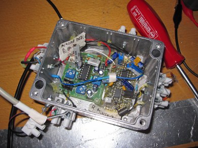
Some pictures
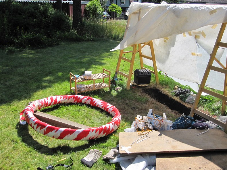
Loop ready for
“grounding”. On the bench box and FM transmitter.
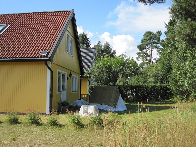
The house and loop
tent (brown), the small tent content car battery and
DC/DC converter.
On the house roof, a solar panel.
On the house roof, a solar panel.
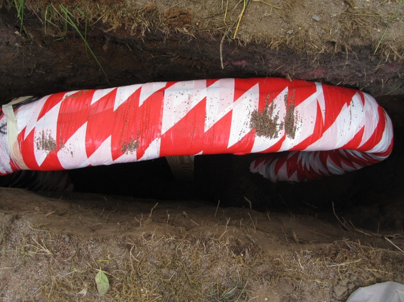
Loop in the hole.
Thanks to:
Renato Romero who helped me to understand Schumann resonances. It is not like receiving signals from a radio amateur station. He also encouraged me to not giving up and go on with the project.
Wolf Buscher, DL4YHF for helping me with Spectrum Lab.
Return to vlf.it index