Half a decade or more ago
my friend, Scott Fusare, wrote an excellent article for the Lowdown called:
Some Thoughts on E-field Whistler Receiver Design. After reading Scott's
article on followers for VLF receiver front ends I began in earnest to
build and test a great many designs. Over the last four years experiments
with a wide variety of JFET follower inputs brought much success. In the
last year I have used OPAMP Follower input stages exclusively in an effort
to accomplish the most work with the least expense. Correspondence with
Scott and information sharing made this work most enjoyable. It is with
great pleasure I thank Scott for his most excellent idea on Follower Input
Stages and the LC filter designs used throughout the Spectrum 1 VLF Receiver.
Please check out Scott's Lowdown article mentioned above or contact him
at: sfusare@adelphia.net. I
have saved the article in pdf format if you are unable to find it elsewhere.
Read it. There is a great wealth of information in the article.
Spectrum 1 VLF Receiver.
Format: Very high input impedance OPAMP follower based on a low noise JFET input OPA134/2134 8 pin dip IC.
Antenna Input Jack, J1, is an XLR-3 type with gold contact plating. This jack provides the extra pin/lead for the Follower driven Inner Guard Shield as well as the input signal and ground. The Inner Guard Shielding is the same as used on Hi-Z Scope input probes. It prevents the otherwise huge signal loss and degradation by eliminating cable capacitance. It is simple and extremely effective. It also allows operation without passive filtering on the input which strips off much of the signal prior to amplification. Introducing the signal to an amplifier is the most critical part of any VLF/Natural Radio design. Extracting signal below anything you've experienced before is very exciting. Using Inner Guard Shielding is a sure way to do this. Read the Fusare Article and then build your own Spectrum 1 VLF Receiver .
There is a little Ne2 neon bulb across the input lead that will let you know when there is a high field voltage around the antenna. Many nights I have experienced voltage arcing continuously across the antenna input jack. When that starts up I go home.
Bootstrapping using the follower output raises the input impedance for AC signals tremendously. A variety of schemes using different values of 1% metal film and 5% carbon film bias resistors in strings from two to four parts have been tested. There is little difference in results so two 4.7 megohm parts were used in my version.
The OPA134/2134 OPAMP has around .01 ohms output impedance and 40-ma current capability and easily drives the 12.5KHz LC low pass filter on the Follower output. Providing bootstrapping bias, Inner Guard Shielding and low output impedance with high drive current and low noise is a lot of work for one device to accomplish. The OPA134/2134 chips do this easily.
500 ohm LC high pass and low pass filters are used throughout this receiver. The first filter is a 12.5KHz LC low pass type feeding the first gain stage set to either +40 or +46db as desired. Following this is the 1KHz high pass filter or bypass switch S2. The record level pot follows this which feeds two nearly identical +20db gain stages in series whose output goes to S5. S5 selects either a 6KHz or 12KHz LC low pass filter. Output from here goes to the Headphone volume control and to the Record Out Jacks; J2 and J3. J2 is a line output level signal rolling off at 20Hz and J3 is the Mic level output which has S6 to choose from either a -40 or -50db pad with each also rolling off at 20Hz.
The Headphone Amplifier, also another OPA2134, is
used as a high output current +20db gain stage with a high current paralleled
follower to double the output drive. This arrangement will easily drive
standard 8 ohm Stereo Headphones with a simple additional trick. The headphone
jack either has to be insulated from chassis ground or you must use the
Nylon 1/4" stereo jack I did to convert the 8 ohm stereo phones to a 16
ohm mono load. This is handily done with this output jack scheme without
modification to the headphones. A grounded jack will not work like this.
This simple dual OPAMP Headphone Amplifier drives a regular pair of 8 ohm
Stereo Headphones with great ease and with far lower noise than LM386 type
amplifiers.
With over 100db total gain and plenty of current
drive this receiver is a pleasure to listen too. However, it is not intended
to drive low-ohm speakers. A DPST toggle switch is used to shut down the
Headphone stage and conserve battery power while listening to a recorder
output. If you listen at times with a friend it's convenient to have this
extra stage and an extra pair of headphones.
Shaping Amplifier response: S4 is a 4 pole, 3 position, rotary switch. It is used to set low frequency roll-off of all four gain stages at once in this manner: Position 1 sets roll-off to 20Hz. Position 2 at 250Hz and Position 3 at 1KHz. Any OPAMP can be used in this manner. Use this formula: 1/2pi®© to arrive at the cutoff frequency desired. One receiver tested used 250Hz, 500Hz and 1KHz roll-off and worked very well having each breakpoint an octave higher. The parts values chosen for the Spectrum 1 Receiver also work well and give a lower range that is within normal hearing but not down to DC response and then offers the listener increasing blocking levels to attenuate AC power line interference. If you can't get many miles from AC power sources this Receiver will really help. Of course if you are interested in response down to DC you can eliminate the 6.8uf capacitors and ground all four 1K resistors in the first switch position. Mark the panel DC and be aware there will be tremendous gain to the lower frequency spectrum including AC power line hum. As it is the Spectrum 1 VLF Receiver has the ability to operate in close proximity to AC power. This is due in part to the cumulative roll-off provided by S4. A single stage is insufficient. Two stages give improved performance and three stages show a marked improvement. I consider three stages the minimum for shaping OPAMP roll-off and including the Headphone Amplifier as the fourth stage rolled off in this manner gives still greater improvement to rejecting AC power line hum. Limitations to this operation would be gain and stage noise. The Spectrum 1 is about optimum in this regard. I listen while driving at night and am amazed at many of the quiet spots where VLF signals are plainly heard even in town while operating with 1KHz roll-off. Some power lines, transformers and street lights will overload the receiver if you are within about 100 feet but once you reach a couple hundred feet the signals pop back into the phones. At two miles distance from local power lines you will hear Whistlers and delicate VLF signals you have never heard before.
Power Supply: The Spectrum 1 receiver operates for 18 to 24 hours continuously from two 12 volt, 7.5 amp, Gel-Cell batteries before recharge. Those are minimum figures. The simplicity of OPAMP use with dual supplies made this purchase an easy sell for me. You can do nearly as well with your car/rig 12 volt battery and one extra Gel-Cell but you must be sure to plug the car battery into the negative ground supply jack. The Gel-Cell must be the positive ground supply or you will have fireworks. Another reason I chose to run on two Gel-Cells.
Making the dual shielded Antenna Cable: So far I've made 8 and 9 foot double shielded Antenna Cables. I don't know how long a cable the follower would drive efficiently but for a typical vehicle I don't see that a longer cable would be necessary. This is a difficult job to be sure so understanding the objectives clearly and executing them properly are necessary. Begin with a good piece of RG-8 mini-coax from Radio Shack or something similar: not the larger real RG-8. Make the center conductor the signal carrier. The RG-8 braid will become the inner guard shield and will only be connected at the receiver to the output of the follower through S1. This will show how much signal is lost or retrieved and makes a very good demonstration. Outside of this RG-8 you will have the second braid installed and connected to ground. The vehicle body, Antenna carrier, earth ground and the Receiver's ground. On the receiver end, XLR-3 plug and jack, you should use this convention: Pin 1 and the shell of the jack, J1 and plug, is ground. Pin 2 is the Inner Guard and Pin 3 is the Signal input. My friend, Dave Oxnard, in the Netherlands has one of my earlier receivers with this same Antenna and feed cables wired the same way. Our equipment is completely compatible and I suggest you make yours the same. Beginning at the Antenna end of the cable you should assemble a PL-259 plug by cutting the center lead just as you would for an ordinary connection. However, the RG-8 braid must be cut short and covered with heat-shrink tubing and shrunk with heat to prevent any contact of this braid with either the outer shield ground or the signal conductor. Failure to understand or do this will result in zero signal reception due to shorting the output of the follower. The RG-8 coax braid can only be connected to the Follower output on the Receiver end when you plug the Antenna into the Spectrum 1 Receiver Jack, J1. You may have to open up the UG-174 cable adapter for the PL-259 or make your own to install the dual shield cable into the adapter and attach the cable to the PL-259. You can solder the outer braid to the adapter and thread the fit cable into the PL-259 and finish the signal connection by soldering the center lead to the tip. The Antenna end of the cable is finished. Use a SO-239 jack on the Antenna mount to connect your cable to the Antenna. At the Antenna all that is connected is the center of the RG-8 and the new outer braid/ground. To make the connections of both shield braids and the center conductor at the XLR-3 plug takes a bit of extra effort. It is necessary to shove both the inner coax and the loose outer shield braid through the XLR-3 plug. The method I use is handled by making a two piece funnel. A piece of rifle cartridge brass sawn in half lengthwise with the head removed after works well. You assemble the two halves over the dual shield cable and tape the funnel tightly and then shove the cable through the XLR-3 plug. Remove the funnel pieces. A little STOS synthetic lube will also help. All of the cables I've made so far have worked perfectly. If you follow all this and do likewise yours will too. Be sure to carefully insulate the inner guard shield from shorting inside the XLR-3 plug.
OPAMPS that work: The only critical amp in this receiver is the Input Stage Follower. One can use either the single package device; OPA134 or the dual OPA2134. There are many other low noise OPAMPS that will give excellent operation for the remainder of the receiver. I favor the OPA2134 above all other possibilities and it does many other jobs in audio work equally well. I recommend purchasing 25 from Digi-Key to get a price break. You'll use them up in projects before you know it. Eventually I will design a PCB for this receiver using the three OPA2134 system and post it here as well. This receiver has been a work in progress for over four years and after much field testing, revision and modification it has become a very exciting VLF Receiver project to work on and listen too. Comparing it to other VLF receivers I have built or used, especially those using JFET common source input stages, I am able to hear VLF signals well below any other receivers noise floor with the Spectrum 1 VLF Receiver in side by side testing. Please feel free to contact me if you have questions or want assistance in building your own version. See at: http://www.vlf.it/directcontact/directcontact.htm
Parts Sources: Everything used in the Spectrum 1 VLF Receiver can be purchased from Mouser and Digi-Key. Check the Parts List. Here is a terrific Filter Design Site: www.wa4dsy.net/filter/hp_lp_filter.html. I use this Site to quickly work out LC filters for Audio to RF applications. It's a great resource. 1% metal film resistors were used for most of this receiver. Only one input and one output capacitor are used from Antenna Input to Record or Headphone output. I consider the input capacitor essential help against high voltage DC fields but the output capacitor is optional. I regularly read zero volts on the Headphone Amplifier output due to the laser trimming of these OPAMPS. The two 33 ohm output resistors and 220uf output capacitor block DC and roll-off at 20Hz. Best of luck to all VLF listeners in all you do and hear. Be sure to use good bypass caps on all power supply pins. I used 1uf/50V tantalums throughout. Be sure to watch polarity. They will explode if connected backwards.
Spectrum 1 VLF Receiver Parts List
Parts are from Mouser unless noted
C1 .01uf polyester film cap 100V 140-PF2A103J
C2, 3, 23, 24 .039uf polyester film 2% 100V
140-PF2A393F
C4 .1uf metallized polyester 5% 100V
5989-250V.1
C5, 6, 12, 16, 20, 31 .15uf metallized polyester
5% 100V 5989-250V.15
C7 .1uf polyester film 2% 100V 140-PF2A104F
C8, 9 33pf 5% NPO ceramic 140-50N5-330J
C10, 14, 18, 29 6.8uf non-polar electrolytic 50V
140-NPRL50V6.8
C11, 15, 19, 30 .47uf metallized polyester 5% 100V
5989-250V.47
C13, 17, 28 330pf 5% ceramic 140-50S5-331J
C21, 22 .082uf polyester film 2% 100V 140-PF2A823F
C25 22uf non-polar electrolytic 50V
140-NPRL50V22
C26 .82uf metallized polyester 5% 100V
5989-250V.82
C27 .22uf metallized polyester 5% 100V
5989-250V.22
C32 220uf 50V electrolytic 140-XRL50V220
C33, 34 .002uf polyester film 2% 100V parallel
one each with C23, 24
To make
.041uf for 12KHz Low Pass Filter. 140-PF2A202F
IC1, 2, 3 OPA2134 dual JFET Input Opamp Digi-Key
OPA2134PA-ND
J1 XLR-3 Jack Antenna Input and Inner
Guard Shield Output
Gold pins, Nickel shell. 174-7153
J2, 3 3.5mm miniature phone jacks for
Record Outputs 502-41
J4 Nylon 1/4" Stereo Phone Jack. Makes 16 Ohm load
out of standard 8 Ohm Stereo Headphones and isolates ground.
Rean 568-NYS218
J5, 6 2.5mm DC Power Supply Jacks. Kobiconn 163-4303
L1, 3, 9, 11 8.2mH shielded inductor Fastron 434-02-822J
L2, 10 15mH shielded inductor Fastron 434-02-153J
L4, 5 68mH shielded inductor Fastron 434-02-683J
L6, 8 18mH shielded inductor Fastron 434-02-183J
L7 27mH shielded inductor Fastron 434-02-273J
R1, 21 100 ohm 1% metal film 271-100
R2, 3, 7, 12, 15 499 ohm 1% metal film 271-499
R4, 5 4.7 megohm 5% carbon film 291-4.7M
R6 160 ohm 1% metal film 271-160
R8, 9 100K ohm 1% metal film 271-100K
R10, 14, 17, 24 1K ohm 1% metal film 271-1K
R11, 22 500 ohm linear taper potentiometer Alpha
24mm 31VA205
R13, 16, 19, 23 10K ohm 1% metal film 271-10K
R18 330 ohm 1% metal film 271-330
R20 33K ohm 1% metal film 271-33J
R25, 26 33 ohm 1% metal film 271-33
S1/3 Miniature SPST toggle switch (testing of guarding/shielding)
Mouser 10TC220
S2/5 Lorlin Rotary switches. 2 pole up to 6 position.
Mouser 105-13572
S4 Lorlin Rotary switch. 4 pole 3 position. Mouser
105-14574
S7 Mouser DPDT toggle switch 10TC260
S6 eliminate switch and all associated using
only the output resistor and cap to the line out jack. Set gain/recording
level lower for mic level input recorders.
Stormchaser Antennas
Ive been using a copper tubing, door mounted, Antenna
system for Mobile Natrad Reception almost 6 years now and since 2003 it
has incorporated a guarding/shield system with an Opamp follower Input
to eliminate the coaxial cable capacitance. This requires a 3-wire cable
system with internal guarding shield powered by the Opamp and an external
ground shield. Using RG-8 for the signal and guarding shield and adding
an outer braid shield over this for the ground shield provides the necessary
double shielded Coax. Some of the available Jack/Plug systems that work
well for this are Stereo ¼ types, 2 pin BNC and XLR-3 to name a
few. I wanted to use Gold contact Jacks and Plugs so I chose the XLR-3s
for all my equipment. To operate a typical JFET input Receiver like the
BBB-4 or one of the INSPIRE Receivers with a coaxial cable feed would be
giving up about 90 percent of the available signal to the huge cable capacitance
before it ever arrives at your Receiver. The way around this is a strong
Opamp Follower system performing the same function Hi-Z Scope probes use
for their input cables. It works.
 |
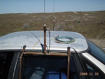 |
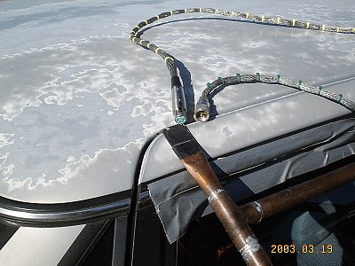
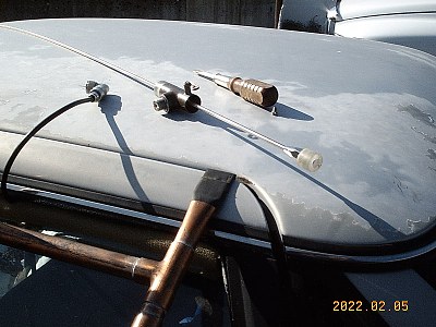
From the photos of my car, Stormchaser, and the
copper tubing antenna carriers you should be able to realize a system of
your own manufacture comprised of ¾ copper tubing, fittings, a
nice Radio Shack 102 Stainless Steel CB antenna, some coax, an extra braided
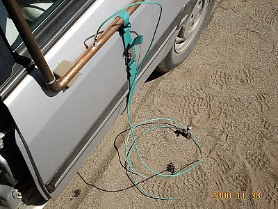
ground shield and something like the XLR-3 Jack and Plug. I made a simple
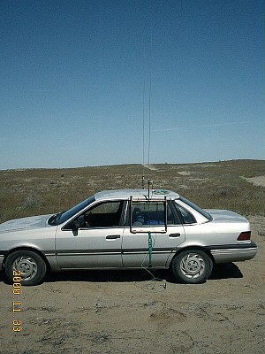
box tubing framework and some homemade folded hooks to set over the top
of my 1991 Ford Tempo; Stormchaser. Ive also made similar hooks out of
the same 1/8 thick by 1 ½ wide steel strapping to mount to the
top of car windows. Either method works and will support the antenna perfectly
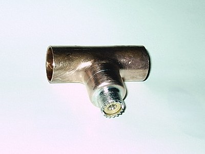
even up to speeds of 70+ mph. Notice the antenna has a plastic insulator
in the top of the ¾ T. It also has a plastic insulator on the end
down inside the tubing riser. Teflon would be the best insulator material
but regular Plexiglas or lexan works equally well and will be much easier
to find. I installed several banana jacks on the door carrier crossbars
to couple my antenna system to the vehicle body and ground. Another Jack
is used to allow plugging in a grounding strap from either side of Stormchaser
to 8 foot ground rods I have planted in various listening spots in Washington
State. I carry other ground rods and hammers with me to install temporary
grounds wherever I travel to do Natrad listening and recording. I also
drive listening to my Spectrum 1 Natrad Receiver looking for quiet spots
without AC power interference. Youd be amazed at how many locations offer
listening possibilities if one has a good high pass filter in the Receiver.
In my neck of the woods I rarely get more than 2 miles from local AC power
lines although I have enjoyed one instance in Oregon that was around 20
plus miles from power. That indeed was a treat to operate with audio response
down to 20 Hz.
 |
 |
If you are a good craftsman you will have no trouble
assembling a system similar to mine and if not get acquainted with someone
who possess the necessary skills for help or jump in and get the experience
yourself. Fabrication of the carrier and the plug-in Antenna will require
a 10-foot length of copper tubing, A tubing cutter, solder and paste and
a small Propane Torch. To tie it down to the door I used 1 wide Nylon
strap and a few plastic slides and a buckle as well as making a J-hook
also out of flat steel as above to anchor the bottom of the carrier to
the bottom of the car door. Place some regular split foam insulation anywhere
the tubing rubs the car and you will avoid damaging the paint. I disassembled
a number of Banana Jacks and Plugs to make up all the grounding straps
with 10 gauge stranded copper wiring and a few big Plated clamps to connect
to my ground rods. Drill holes where you want the grounding Jacks and solder
them in place. Also include two ground posts for the Antenna T and Riser
tubing.
|
 |
By directly grounding the two together you will
avoid loss of ground between the carrier and Antenna along with severe
signal degradation. Finally a good Epoxy 2 part glue will be handy for
the top plastic insulator in the T fitting. There is plenty of room to
mount an SO-239 Jack in the Antenna T and also solder the center pin to
the antenna.
 |
All simple stuff and readily available at most
hardware stores at least throughout the USA. The final task is making the
Antenna cable. At the Receiver you will have 3 connections to make; Signal,
Guarding Shield and Ground Shield. Use standard XLR wiring format.
On the Antenna end of the cable you will only connect the outer shield/ground braid and the center conductor of the Coaxial cable. The Plug and Jack I use are UHF types. PL-259/SO-239. You must not connect the braid of the coaxial cable to anything at the Antenna. That Braid is connected only to the Opamp to provide Guarding. Slip on a small piece of heatshrink tubing and heat it to shrink and protect the RG-8 braid from shorting to ground. On my Receivers I use a simple toggle switch to shut off the Guarding. Such a simple demonstration makes a believer out of anyone immediately. Without Guarding a 9 foot coaxial cable delivers very little signal. With Guarding the results are very impressive. |
Check out the photos to see what all this looks
like.
If you need any assistance you can reach me via
e-mail.
See at: http://www.vlf.it/directcontact/directcontact.htm
Dave Ewer