1. Loop Amp with negative input resistance
2. Some more general discussion
Loop Amp with negative input resistance
The first part of this article dicusses an improvement to the loop antenna which was introduced by Marco Bruno in his article Thinking about IDEAL LOOPS. Please read that article first.
With my observations of sferics and environmenmtal magnetic fields I sometimes felt upset by the very loud sferics in contrast to the sounds of lower frequencies. You probably know that even very short but loud clicks can cause permanent damage to the ear, especially when using headphones. Then I realized that the induced voltage from an open loop antenna is proportional to frequency and since then I was convinced that some kind of integration on the signal would be necessary. So I felt confirmed when I read Marco Bruno's article. Although his idea seems promisingto me, I must admit I have not tried it until now. So this text simply exposes my own ideas on that topic.
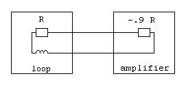
With Marco's loop antenna there exists a limitation in bandwith to the lower end of the spectrum which made me think further. If the lower border of bandwith is defined from the term R/(2*p*L), then it can be lowered by decreasing of R, which is the sum of resistances of the loop's wire, the cable to the amplifier and the amplifier's input resistance. Marco made the amplifier's input resistance near zero, but if we can make it negative, the resulting over all resistance can approach zero as well. A negative over all resistance must be avoided and a value very near to zero can cause stability problems, so I propose a reduction to one tenth of the loop's resistance here. This figure shows the combination of resitances in the input circuitry:
The resulting sum of these resistances is 1 R -0.9 R = + 0.1 R. This will decrease the boundary frequency to 1/10 of its value as with a zero Ohm input resistance. Marco's circuitry can be expanded to exhibit such a behavior. But first I want to explain what a negative resitance means in practise. With a normal resistor of positive resistance a positive voltage applied to it causes a positive current to flow into the device. With a negative resistance, the same voltage will cause a current in opposite direction flowing out of the device. Another description says that a positive current flowing into the device will cause a negative voltage at its terminals. The simple definition is that the ratio of U/I is negative. This can be achieved by using an active device like an operational amplifier:
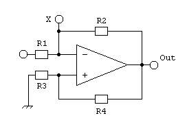
Let's have a look at the point X. A positive current flowing into the circuit causes a negative voltage at the amplifier output, a portion of which is returned its noninverting input. The OpAmp in turn balances its inputs to equal potentials via feedback along R2. Thus a negative voltage arises at point X and the apparent input resistance of the whole circuit is negative. Now imagine R1 to be the resistance of the loop antenna's wire, wich is connected to ground at the other end. Then the negative feedback is defined by R1 and R2 and the circuit operates stable only if
(1) R4 / R3 > R2 / R1.
We are now going to calculate the apparent resistance at point X:
(2) RX = UX / IR2
(3) IR2 = (UX - UOut)/ R2
The OpAmp serves for
(4) UX = UOut * R3 / (R3+ R4)
and we transform this into
(5) UOut = UX * (R3 + R4) / R3
We put (4) into (3):
(6) IR2 = (UOut * R3 / (R3+ R4) - Uout) / R2
and get
(7) IR2 = - UOut * R4 / ((R3+ R4) * R2)
Putting (5) into (7)
(8) IR2 = - (UX * (R3 + R4)/ R3) * R4 / ((R3 + R4) * R2)
gives us
(9) IR2 = - (UX * R4/ (R2 * R3)
Finally putting this into (2)
(10) RX = UX / - (UX* R4 / (R2 * R3)
results in
(11) RX = - R2 * R3 / R4
Let's apply this to the loop amplifier. In Marco's example the loop wire's
resistance R1 is 3.5 W and R2 is 20.4 kW.
When we want the circuit to have an input resistance of -0.9 * 3.5 W
= -3.15W then (11) says
-3.15 W = - 20.4 kW
* R3 / R4 which resolves to R4 / R3 = 6476.
As the resulting resistor from R3 in parallel with R4 causes additional noise to the noninverting input, we want to keep its value low and set R3 to 10 W for example. The noise contribution from R4 can be omitted. Thus R4 becomes 64.76 kW.
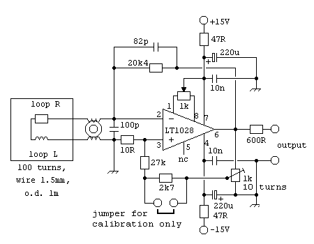
Special attention has to be payed to the fact that we are operating the circuit close to the region of instability and the loop and the cable to the amplifier are part of it. Therefore the amplifier must be mounted very close to the loop and the cable between them has to be stable and protected from unnecessary deforming movements. The connections should be soldered without use of any jacks. Furthermore the resistors R2, R3 and R4 must be of low tolerance and good temperature stability. Another problem is to determine the exact value of the loop wire's resistance. To overcome that problem, I suggest to adjust the circiut with a trimmer by finding the point of instability as a reference and then decrease the positive feedback along R4 by a well defined percentage. My circuit utilizes a jumper for that task and with R4 = 27 kW a wire resistance up to 8W is supported. In order to prevent unwanted oscillations, a capacitor in the feedback line should only be used to the inverting input.
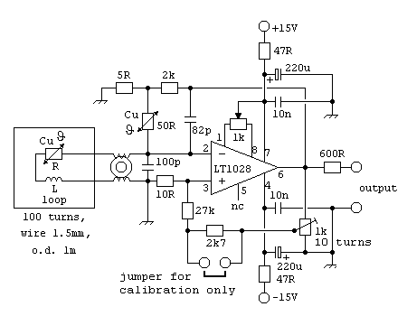
Here is my proposal for a circuit, which is just a modification from Marco's work:
Even with the most deliberate design of the device there still remains another problem within the loop itself. Marco Bruno pointed out the temperature dependence of the loop's copper wire. Regarding all possible weather conditions and loop temperature, variations of the loop resistance can cause variabe gain and thus also stability problems. Therefore I introduced temperature compensation using copper as sensor again. For this task we need a resistor made of a long thin copper wire as a reference. It can be wound to a coil, but the inductivity must be minimal and this coil should not be a receiver for magnetic signals. Therefore befilar windings are ideal. The principle of a thus temperatue compensated input amplifier looks like this:
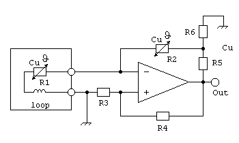
The copper resistor will be of a much smaller valuethan 20kW, therfore an adequate reduceded proportion of the output voltage is to be provided by the matching network R6/R6. Its output impedance must be much smaller than R2 in order not to diminish its effect. So R6 has to be of very small value, but on the other hand it is limited by the maximum load to the OpAmp's output. Assuming we can make a copper resistor of 50W, the final circuit using it can be like this:
Some more generaldiscussion
The working principle of the above described loop antenna still inherits
a lower boundary to the frequency range which can be received. I also suppose the positive
feedback leads to amplfication of the OpAmp's intrinsic noise at low frequencies but I havn't
calculated that. The only benefit from my modifications on Marco's design seems to be an
increased gain for low frequencies but no substantial improvement of signal/noise ratio.
At least this can help to avoid a loss in s/n along further processing.
Therefore I still believe this is not yet the best possibility to receive
very low frequencies.
Another aproach also seems very interesting to me: Amplification of the voltage from an open loop and performing an integration on that signal. Although an Integrator also has a lower boundary on its range of working frequencies, this can be set arbitrary and is not determined by the loop. The problem of covering a very large spectrum with an integration function can be solved by cascading multiple integrator stages for different parts of the spectrum, some of them can even be passive filters. Integration will nearly solve the problem of the lower cutoff, because it can be set at any desired frequency, but the problem with noise will not be affected.
When entering the frequency range around 1 Hz, another source of noise becomes important to the performance of the installation, which is the low frequency 1/f noise generated by the amplifier itself. The operational amplifier has to be selected not only by its noise performance in the audio range but also by its frequency of the noise corner. Below that frequency the 1/f noise rises above the white noise floor. The LT1028 seems to be very siutable with a corner frequency of typically 3.5 Hz. As this kind of noise becomes predominant towards lower frequencies, it can be further lowerded by using multiple amplifiers in parallel.
The hardest restriction to the reception of low frequencies with loops ist given from the fact, that the induced voltage is proportional to f. To obtain good signal quality, another type of sensor will be necessary. There are fluxgate magnetometers which provide continuous output and proton precession magnetometers which are of best sensitivity. I wonder wether the latter could be made to produce continuous output as well!? I found that Dan Fountain and Phil Barnes have put some interesting pages about homebuilt proton precession magnetometers to the web and another from a fellow whose name I could not find.
Last not least I want to introduce a solution to a very common problem in listening to environmental magnetic fields: Hum from the powergrid is nearly everywhere present and can easily superimpose weaker signals. In spite of telling the whole story here again, I just invite you to read the description (within another context) on my homepage. The idea is not unique as I found that others also had it, but I could not find much publication about it and it works well.
If you try any of the proposed ideas I would like to read obout your
results. Please write to this address.
Good listening!
Peter Schmalkoke, May 2001