From some of months my interest was captured to the challenge of receiving some exotic signals in the range of ELF SLF ULF VLF frequencies. Connecting an antenna to a PC with a Sound Card and Software like CiaoRadio, it is possible to receive, analyze, and demodulate any ELF SLF ULF VLF signal up to 24 kHz.
STATE OF THE
ART
Many antennas for the VLF and ULF use have been
developed so far. Numerous examples can be found for example at www.vlf.it
, plus, I have already developed and described the ADA (Active Differential
Antenna) , now in the antenneX archives. The same theory is applied here
to develop an active interface and an antenna based on the well-known
Marconi Long Wire.
The antennas at these frequencies are vertically polarized in 99% of the case. The mode of propagation is the Surface Wave where the vertical wave could travel. Every horizontal component is mainly cancelled from the anti-phase reflection of the ground.
Horizontal polarization looks to be used only to receive the seismic precursors and the signal coming from the sky wave of the auroras that have random polarizations. Most of these antennas are based on the use of Short Monopoles (with or without capacitive hats) or Small Loops as in Figure 1.
Figure 1: Small Loops and short
Monopoles used in VLF and ULF receiving stations.
Both are typically untuned. The monopoles are typically connected to high impedance amplifiers and the loops are typically connected to low impedance amplifiers as in Figure 2.
Figure 2: Short Monopoles or Small Loops connected to Operational Amplifiers for Broadband operation
This allows the antennas to have very large bandwidth behaviour. The problem with the monopoles is that the ground system that recreates the lower part of the dipole is very fuzzy. This means that local currents induced from the main at 50 or 60 Hz and harmonics could easily flow into this undefined part of the antenna. This reduces the possibility to shield the antenna from these high level fields from the main at 50 or 60 Hz and harmonics. One possible way to avoid this is to use a short vertical balanced dipole as probe. To avoid the use of a balun made with inductive parts that will limit the bandwidth at this frequency, it is possible to use a differential amplifier in the so-called configuration of Amplifier for Instruments. The use of Operational Amplifiers allows a high level of peak to peak handling and of intermodulation immunity. This was the road used to develop the ADA (Active Differential Antenna), now in the antenneX archives. This project will now use the same theory to develop the active interface for a Marconi Long Wire antenna.
DESIGN OF THE ANTENNA AND OF THE ACTIVE PART
A short monopole (l < 0.1WL) has an effective eight (H) approximately equal to his length (L). The equivalent circuit, connected to the amplifier is shown in Figure 3.
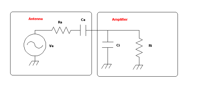
Figure 3: A short monopole equivalent circuit connected to an amplifier
Ra , that is. the radiation resistance , is very low and tends toward zero while the frequency is decreasing and is in any case negligible respect to Ri, that is, the input resistance of the amplifier . If we apply the Thevenin transformation, we get the simplest possible circuit showed in Figure 4.
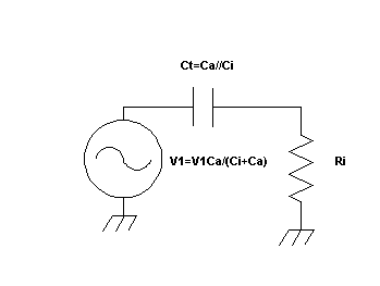
Figure 4: Equivalent circuit of
the antenna and input amplifier
The amplitude of the equivalent generator is decreased from the partition between Ca and Ci, but the equivalent capacitor Ct is the parallel of Ca and Ci. Ri and Ct state the lower frequency Fc. As Ri and Ci increase, the Fc decreases.
Fc = 1/(2PI Ri Ct)
Just as an example, if we have:
Ca = 30 pF
Ci = 0
Ri = 100 MOhm
Fc = 53 Hz
To arrive to 5 Hz, we have to increase the total
capacitance Ct until reaching 300 pF. Being that 100 M? is a value difficult
to increase, going down to 5Hz could be achieved in three ways:
- Increasing the diameter or the length of the
dipole 0
- Using a capacitive hats on top of the dipole
- Increasing the input capacitance of the amplifier
The first method is fairly easy, if not of physical
construction. The second one could easily give microphonic effects if the
hats and the vertical element are not perfectly steady. The third one will
decrease the signal at the input (that in any case is typically is not
so low). With these considerations, either methods or a mix of them could
be used to decrease the minimum frequency of the antenna to 5 Hz, in the
attempt to reach the frequencies from 7 to 42 Hz, range where we have the
Schumann resonances (Earth that acts like a spherical cavity, excited from
lightning). See http://www.vlf.it/Schumann/schumann.htm
Earth-ionosphere
cavity
In
first order approximation, the Earth-atmosphere system can be seen from
an electromagnetic point of view as a radial shell of three layers of conductivity.
The Earth and the ionosphere in about 100-150 km height appear as a perfect
conductor with the air of negligible conductivity in between. They form
a spherical shell of conductivty, denoted Earth-ionosphere cavity, in which
electromagnetic radiation is trapped. Lightning strikes within the
troposphere
radiate energy into this system and the waves are travelling around the
Earth. In the case of constructive interference, Earth-ionosphere
cavity
resonances are excited in the frequency range of 6-60 Hz....
In this case, we will develop the active interface for a Marconi Long Wire antenna.
THE MARCONI LONG WIRE: L, T AND T WITH CAPACITY HAT
The three different designs are shown in Figure 5.
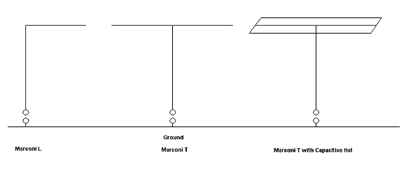
Figure 5: The three different designs of the Marconi Long Wire antenna
The Marconi L is sensitive to both vertical and horizontal polarization. The Marconi Ts are sensitive only to vertical polarization due to cancellation of the currents on the horizontal part. In between, we can find the asymmetrical Marconi T, shown in Figure 6.
Figure 6: The asymmetrical Marconi T
This design is quite the most used because it easily fit in any configuration of ground and house.
HOW TO EVALUATE AND MEASURE THE CAPACITANCE OF THE MARCONI ANTENNAS AT LOW FREQUENCIES
There are some formulas, but a very practical and
quite precise rule of thumb for a wire antenna is to account about 10pF/m
for any wire segment length. A practical way to measure the capacitance
is to resonate the antenna with a know inductance. I performed this test
on the Marconi L antenna of 40 m of total length I built for this use.
With an inductor of 650uH I got a resonance at 305 kHz.
Using the formula:
C=1/((2PIFo)^2*L)
I measured a capacitance of around 420 pF. Resonance
was checked using a variable frequency generator and testing peak of the
current with a series transformer and an oscilloscope.
ACTIVE PART DESIGN
There were two goals:
1) The use of selective components directly after the input to avoid overload of the active components
2) The use of a MOSFET in the first stage of the active part, to guarantee high impedance and low noise. Some Operational Amplifiers have bad noise performances when use with high feedback.
I used the RFSIMM99 freeware for modelling. First check was simply the lower frequency corner of the amplifier excited from the capacity of the antenna, like shown in Figure 7 and 8. I used an ideal OPA as active component. Figure 7 shows the equivalent circuit and Figure 8 the simulation where we can see the lower corner frequency of 3.7 Hz.
Figure 7: The first equivalent
circuit
Figure 8: Simulation with the lower corner frequency at 3.7 Hz
At this stage I decided to add at the input a two-pole RC low pass filter to limit the BW. This added a loss of 2.4 dB, but gave an upper corner frequency of 330 Hz and a slope of 12dB/octave. Circuit and simulation are shown in Figures 9 and 10.
Figure 9: Second circuit with a
two pole RC filter at the input
Figure 10: Simulation of the second circuit with the upper corner frequency at 330Hz
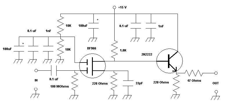
THE REAL ACTIVE AMPLIFIER
Figure 11 shows the real circuit of the active high impedance amplifier. The gain was measured to be 12 dB to 10 MHz and 8 dB at 30 MHz. Removing the RC filter shown in the simulation, this allows the system to perform as an active antenna on the entire HF band. Using the RC filter as in the simulation, we have an active antenna for the band 4-300 Hz. It is possible to switch in and out the filter with a double switch.
THE SCHUMANN RESONANCE OF THE EARTH RECEIVED
Figure 12 shows the practical tests with the Marconi L Long Wire connected to ground, the passive RC filter, the amplifier and the Sound Card of the PC using the CIAORadio software.
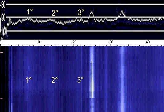
Figure 12: The Schumann Earth Resonance received
The first three resonances were clearly visible on the spectrum and on the spectrogram. The rise of the noise is due to the lightning exciting the Earth-ionosphere like a spherical cavity. Other peaks at 25 Hz and around 33 Hz are man made pulse modulation of the main at 50 Hz (not shown).
CONCLUSIONS
We have shown a simple way to receive the Schumann
Earth Resonances. In the same way it is also possible to receive the signals
from the Russian Submarines at around 82Hz. http://www.vlf.it/submarine/sbmarine.html
By changing the values of the RC circuit or removing
it, it is possible to use the antenna from 4Hz to 30 MHz and up!
In conjunction with a PC with a Sound Card and
the CiaoRadio Software http://www.comsistel.com/Ciao%20Radio.htm
one can receive, analyze and demodulate any ELF SLF ULF - VLF signal
to 24 KHz, like shown in the article of the ADA (Active Differential Antenna)
now in the antenneX archives.
This article has been publish also
on antenneX Online Issue No. 105 January 2006 Copyright ©
1988-2006 All rights reserved - antenneX©